How to Use JQ6500: Examples, Pinouts, and Specs
Introduction
The JQ6500 is a versatile and high-quality audio playback module designed for embedded audio applications. It supports popular audio formats such as WAV and MP3, making it suitable for a wide range of projects requiring sound playback. The module features a built-in amplifier, a microSD card slot for audio file storage, and multiple control interfaces, including UART and GPIO. Its compact size and ease of use make it a popular choice for DIY electronics, IoT devices, and interactive systems.
Explore Projects Built with JQ6500


Explore Projects Built with JQ6500
Common Applications
- Voice prompts and sound effects in embedded systems
- Interactive kiosks and vending machines
- IoT devices with audio feedback
- Educational and DIY electronics projects
- Alarm systems with custom audio alerts
Technical Specifications
Below are the key technical details of the JQ6500 module:
| Parameter | Value |
|---|---|
| Supply Voltage | 3.3V to 5.0V |
| Current Consumption | 20mA (idle), up to 200mA (active) |
| Audio Formats Supported | MP3, WAV |
| Storage | MicroSD card (up to 32GB) |
| Control Interfaces | UART, GPIO |
| Built-in Amplifier | Yes (3W mono output) |
| Audio Output | Speaker (via amplifier) or AUX |
| Operating Temperature | -40°C to 85°C |
| Dimensions | 20mm x 20mm x 8mm |
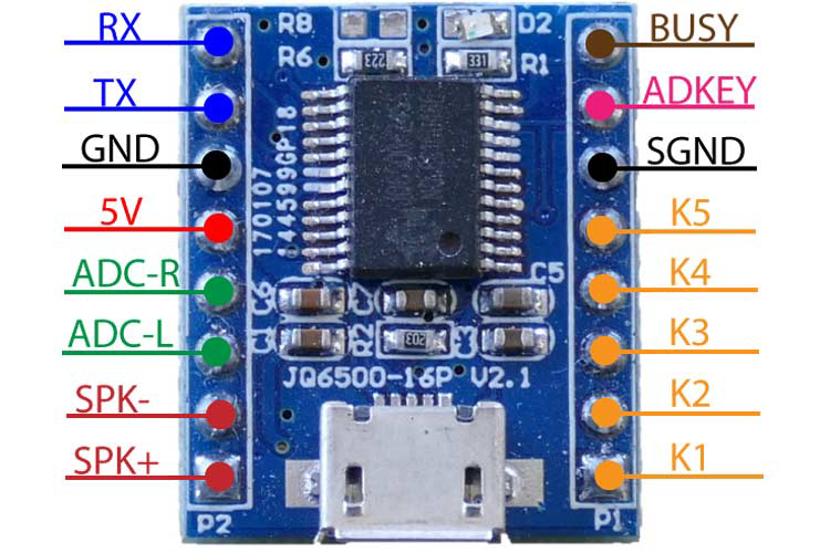
Pin Configuration and Descriptions
The JQ6500 module has a simple pinout for easy integration into circuits. Below is the pin configuration:
| Pin | Name | Description |
|---|---|---|
| 1 | VCC | Power supply input (3.3V to 5.0V). |
| 2 | GND | Ground connection. |
| 3 | TX | UART transmit pin (used for communication with a microcontroller). |
| 4 | RX | UART receive pin (used for communication with a microcontroller). |
| 5 | SPK+ | Positive terminal for speaker output (amplified audio). |
| 6 | SPK- | Negative terminal for speaker output (amplified audio). |
| 7 | IO1 | GPIO pin 1 (can trigger specific audio files when configured). |
| 8 | IO2 | GPIO pin 2 (can trigger specific audio files when configured). |
Usage Instructions
How to Use the JQ6500 in a Circuit
- Power Supply: Connect the VCC pin to a 3.3V or 5.0V power source and the GND pin to ground.
- Audio Output:
- For amplified audio, connect a speaker to the SPK+ and SPK- pins.
- For line-level audio, use the AUX output (if available on your module variant).
- Control Interface:
- Use the UART interface (TX and RX pins) to control the module via a microcontroller like an Arduino.
- Alternatively, use the GPIO pins (IO1 and IO2) to trigger specific audio files directly.
- Audio Files:
- Format a microSD card (FAT32 format) and load audio files onto it.
- Ensure the files are named appropriately (e.g.,
0001.mp3,0002.mp3) for easy triggering.
Important Considerations and Best Practices
- Power Supply: Use a stable power source to avoid noise or distortion in audio playback.
- Speaker Selection: Use a speaker with a power rating of at least 3W to match the built-in amplifier.
- File Naming: Follow the module's file naming conventions to ensure proper playback.
- UART Communication: Use a logic level converter if your microcontroller operates at 3.3V and the module is powered at 5V.
Example: Using JQ6500 with Arduino UNO
Below is an example of how to control the JQ6500 module using an Arduino UNO via UART:
#include <SoftwareSerial.h>

// Define RX and TX pins for communication with JQ6500
SoftwareSerial JQ6500(10, 11); // RX = Pin 10, TX = Pin 11

void setup() {
  Serial.begin(9600);          // Initialize Serial Monitor
  JQ6500.begin(9600);          // Initialize JQ6500 communication
  delay(1000);                 // Allow the module to initialize

  // Play the first audio file (0001.mp3)
  JQ6500.write(0x7E);          // Start byte
  JQ6500.write(0x03);          // Command length
  JQ6500.write(0x01);          // Play command
  JQ6500.write(0x01);          // File number (0001.mp3)
  JQ6500.write(0xEF);          // End byte
}

void loop() {
  // Add your logic here to trigger audio playback
}
Notes on the Code
- The
SoftwareSeriallibrary is used to communicate with the JQ6500 module. - The command structure follows the JQ6500 protocol, where each command starts with
0x7Eand ends with0xEF.
Troubleshooting and FAQs
Common Issues and Solutions
No Audio Output:
- Ensure the speaker is properly connected to the SPK+ and SPK- pins.
- Verify that the microSD card is formatted correctly and contains valid audio files.
Distorted Audio:
- Check the power supply for stability and ensure it meets the voltage requirements.
- Use a speaker with the correct impedance and power rating.
Module Not Responding to UART Commands:
- Verify the baud rate (default is 9600) and ensure proper connections to the TX and RX pins.
- Check for loose or incorrect wiring.
Audio File Not Playing:
- Ensure the file is named correctly (e.g.,
0001.mp3) and stored in the root directory of the microSD card. - Confirm that the file format is supported (MP3 or WAV).
- Ensure the file is named correctly (e.g.,
FAQs
Q: Can the JQ6500 play audio without a microcontroller?
A: Yes, the module can play audio files directly using the GPIO pins (IO1 and IO2) to trigger specific files.
Q: What is the maximum storage capacity supported?
A: The JQ6500 supports microSD cards up to 32GB formatted in FAT32.
Q: Can I use the JQ6500 with a 3.3V microcontroller?
A: Yes, the module is compatible with 3.3V logic levels, but ensure the power supply voltage is within the specified range.
Q: How do I adjust the volume?
A: Volume can be adjusted via UART commands or by using external circuitry if supported by your module variant.