
How to Use Sensor board: Examples, Pinouts, and Specs
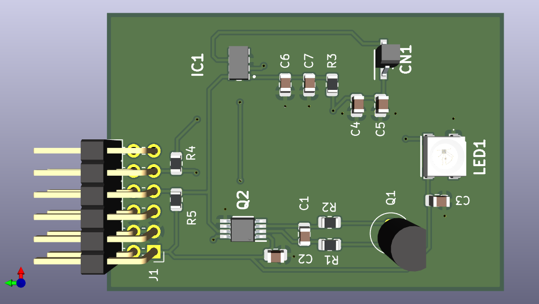
 Design with Sensor board in Cirkit Designer
Introduction
A sensor board is a versatile electronic component that integrates multiple sensors to detect and measure various physical phenomena such as temperature, humidity, light, and motion. These boards often include a microcontroller for processing sensor data and may feature communication interfaces for transmitting data to other devices or systems. Sensor boards are widely used in applications such as environmental monitoring, home automation, robotics, and IoT (Internet of Things) projects.
Explore Projects Built with Sensor board
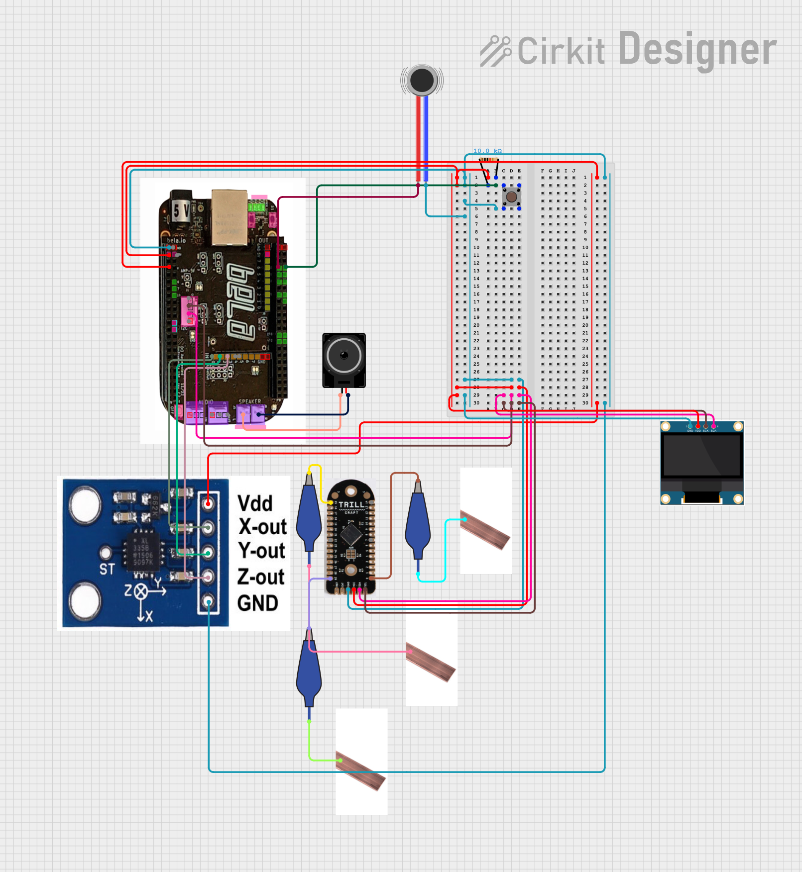
 Open Project in Cirkit Designer
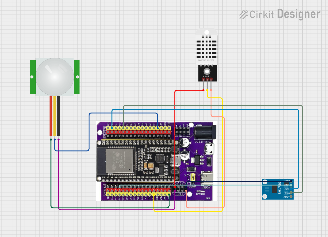
 Open Project in Cirkit Designer
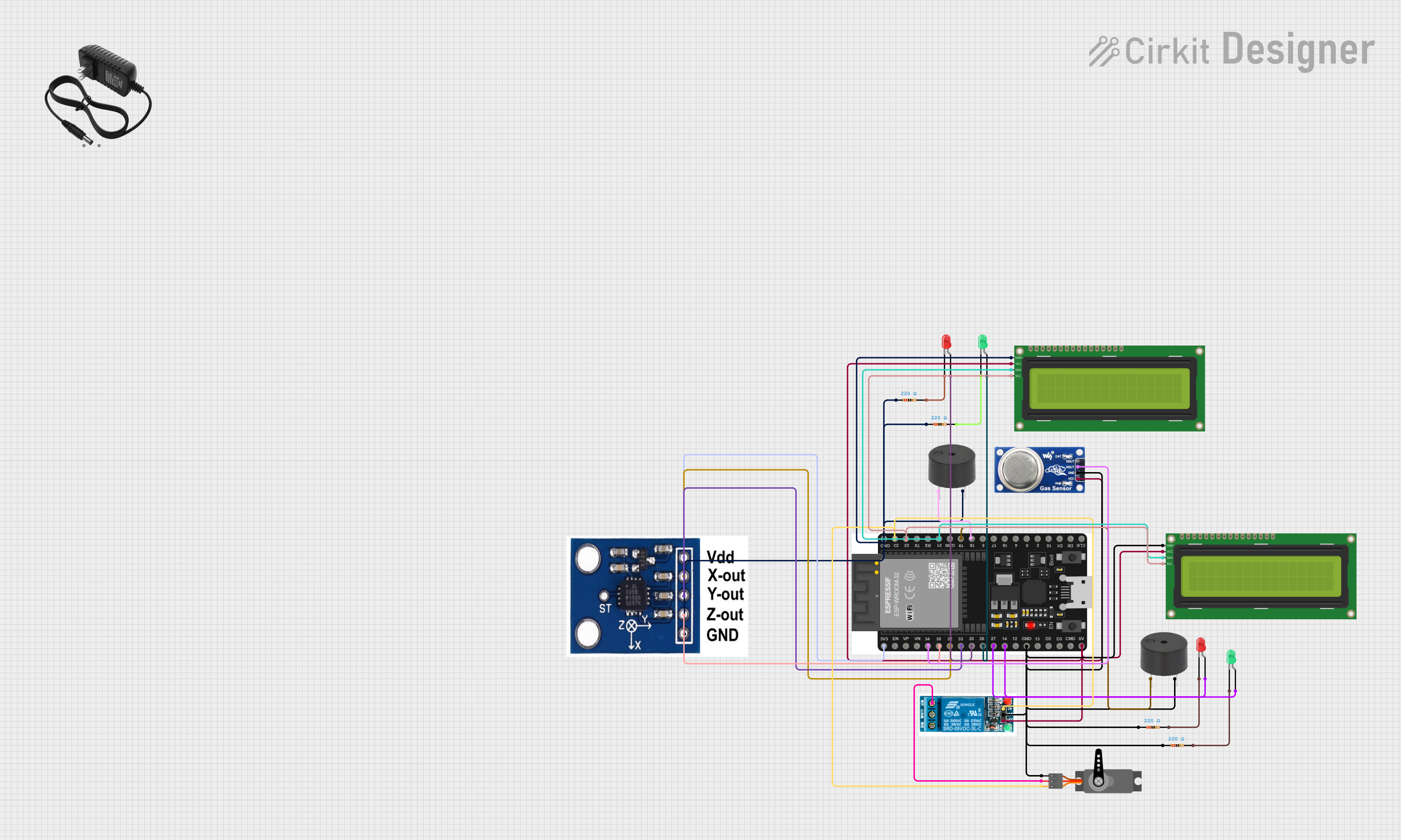
 Open Project in Cirkit Designer
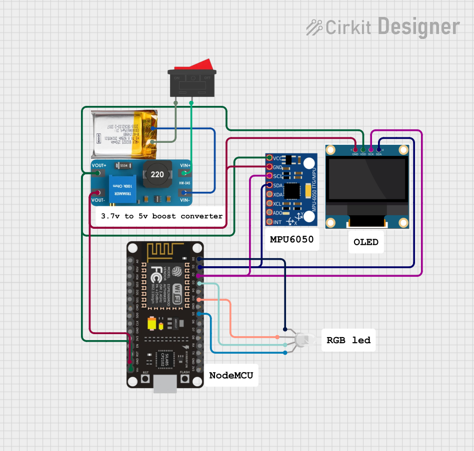
 Open Project in Cirkit Designer
Explore Projects Built with Sensor board

 Open Project in Cirkit Designer
 Open Project in Cirkit Designer
 Open Project in Cirkit Designer
 Open Project in Cirkit Designer
Common Applications and Use Cases
- Environmental Monitoring: Measuring temperature, humidity, and air quality.
- Home Automation: Detecting motion, light levels, or environmental changes.
- Robotics: Providing sensory input for autonomous navigation or decision-making.
- IoT Projects: Collecting and transmitting data to cloud platforms for analysis.
- Industrial Automation: Monitoring environmental conditions in factories or warehouses.
Technical Specifications
Below are the general technical specifications for a typical sensor board. Note that specific models may vary in their exact features and ratings.
Key Technical Details
- Operating Voltage: 3.3V to 5V DC
- Current Consumption: 10mA to 100mA (depending on active sensors)
- Communication Interfaces: I2C, SPI, UART
- Integrated Sensors:
- Temperature Sensor: -40°C to 125°C range, ±0.5°C accuracy
- Humidity Sensor: 0% to 100% RH, ±2% accuracy
- Light Sensor: 0 to 100,000 lux
- Motion Sensor: PIR (Passive Infrared) or accelerometer
- Microcontroller: 8-bit or 32-bit MCU with ADC (Analog-to-Digital Converter)
- Dimensions: Typically 50mm x 50mm (varies by model)
Pin Configuration and Descriptions
The following table outlines the typical pin configuration for a sensor board:
| Pin | Label | Description |
|---|---|---|
| 1 | VCC | Power supply input (3.3V or 5V DC) |
| 2 | GND | Ground connection |
| 3 | SDA | I2C data line for communication |
| 4 | SCL | I2C clock line for communication |
| 5 | TX | UART transmit pin for serial communication |
| 6 | RX | UART receive pin for serial communication |
| 7 | INT | Interrupt pin for motion or event detection |
| 8 | A0 | Analog input pin for external sensors or additional data acquisition |
| 9 | D0 | Digital output pin for triggering external devices (e.g., relays, LEDs) |
| 10 | RESET | Reset pin to restart the microcontroller |
Usage Instructions
How to Use the Sensor Board in a Circuit
- Power the Board: Connect the VCC pin to a 3.3V or 5V power source and the GND pin to ground.
- Connect Communication Lines:
- For I2C: Connect the SDA and SCL pins to the corresponding pins on your microcontroller.
- For UART: Connect the TX and RX pins to the UART pins on your microcontroller.
- Read Sensor Data:
- Use the appropriate communication protocol (I2C, SPI, or UART) to query the sensor data.
- Refer to the sensor board's datasheet for specific register addresses and commands.
- Process Data: Use the microcontroller to process the sensor data and perform actions based on the readings.
- Optional Connections:
- Use the INT pin to detect motion or other events.
- Connect external sensors or devices to the A0 or D0 pins as needed.
Important Considerations and Best Practices
- Power Supply: Ensure the power supply voltage matches the board's requirements (3.3V or 5V).
- Pull-Up Resistors: If using I2C, ensure pull-up resistors (typically 4.7kΩ) are present on the SDA and SCL lines.
- Environmental Factors: Avoid exposing the board to extreme temperatures, humidity, or dust, as this may affect sensor accuracy.
- Code Libraries: Use manufacturer-provided libraries or open-source libraries for easier integration with microcontrollers like Arduino or Raspberry Pi.
Example Code for Arduino UNO
Below is an example of how to interface a sensor board with an Arduino UNO using the I2C protocol:
#include <Wire.h> // Include the Wire library for I2C communication

#define SENSOR_ADDR 0x40 // Replace with the I2C address of your sensor board

void setup() {
  Wire.begin(); // Initialize I2C communication
  Serial.begin(9600); // Start serial communication for debugging
  Serial.println("Sensor Board Initialization...");
}

void loop() {
  Wire.beginTransmission(SENSOR_ADDR); // Start communication with the sensor board
  Wire.write(0x00); // Replace with the register address to read data
  Wire.endTransmission();

  Wire.requestFrom(SENSOR_ADDR, 2); // Request 2 bytes of data from the sensor
  if (Wire.available() == 2) {
    int data = Wire.read() << 8 | Wire.read(); // Combine two bytes into a single value
    Serial.print("Sensor Data: ");
    Serial.println(data); // Print the sensor data to the serial monitor
  } else {
    Serial.println("Error: No data received from sensor board.");
  }

  delay(1000); // Wait for 1 second before the next reading
}
Troubleshooting and FAQs
Common Issues and Solutions
No Data Received from the Sensor Board:
- Solution: Check the I2C address of the sensor board and ensure it matches the address in your code.
- Tip: Use an I2C scanner sketch to detect the board's address.
Incorrect Sensor Readings:
- Solution: Verify that the board is powered correctly and that the sensors are not exposed to extreme conditions.
- Tip: Calibrate the sensors if required (refer to the datasheet for calibration instructions).
Communication Errors:
- Solution: Ensure proper connections for SDA, SCL, TX, and RX pins. Check for loose wires or poor soldering.
- Tip: Use pull-up resistors on the I2C lines if not already present.
Board Not Powering On:
- Solution: Verify the power supply voltage and current. Ensure the VCC and GND connections are secure.
FAQs
Q: Can I connect additional sensors to the board?
- A: Yes, you can use the A0 or D0 pins to connect external sensors, provided they are compatible with the board's voltage and communication protocols.
Q: Is the sensor board compatible with Raspberry Pi?
- A: Yes, the board can be interfaced with Raspberry Pi using I2C, SPI, or UART communication.
Q: How do I update the firmware on the sensor board?
- A: Refer to the manufacturer's instructions for firmware updates. Typically, this involves connecting the board to a computer via USB or a programming interface.
Q: Can the board operate on battery power?
- A: Yes, as long as the battery provides a stable voltage within the board's operating range (3.3V to 5V).