How to Use FREENOVE ESP32 WROVER: Examples, Pinouts, and Specs
Introduction
The FREENOVE ESP32 WROVER E is a powerful microcontroller board designed for a wide range of applications, particularly in the Internet of Things (IoT) domain. It is based on the ESP32 chip, which integrates Wi-Fi and Bluetooth capabilities, making it an excellent choice for projects requiring wireless communication. This board is well-suited for tasks such as home automation, robotics, environmental monitoring, and other embedded systems.
Explore Projects Built with FREENOVE ESP32 WROVER


Explore Projects Built with FREENOVE ESP32 WROVER
Common Applications and Use Cases
- IoT devices and smart home systems
- Wireless sensor networks
- Robotics and automation
- Environmental monitoring and data logging
- Wearable devices
- Prototyping and educational projects
Technical Specifications
The following table outlines the key technical details of the FREENOVE ESP32 WROVER E:
| Specification | Details |
|---|---|
| Microcontroller | ESP32-WROVER-E (dual-core Xtensa LX6 processor) |
| Clock Speed | Up to 240 MHz |
| Flash Memory | 16 MB |
| PSRAM | 8 MB |
| Wi-Fi | 802.11 b/g/n |
| Bluetooth | Bluetooth 4.2 (Classic and BLE) |
| Operating Voltage | 3.3V |
| Input Voltage Range | 5V (via USB) or 7-12V (via VIN pin) |
| GPIO Pins | 36 (including ADC, DAC, PWM, I2C, SPI, UART) |
| Analog Input Pins | 18 (12-bit ADC resolution) |
| Digital Output Pins | 36 |
| Communication Interfaces | UART, SPI, I2C, CAN, PWM |
| Power Consumption | Ultra-low power consumption in deep sleep mode (as low as 10 µA) |
| Dimensions | 58 mm x 25 mm |
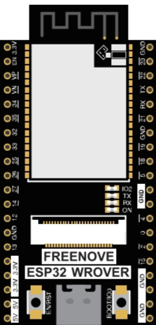
Pin Configuration and Descriptions
The FREENOVE ESP32 WROVER E features a variety of pins for different functionalities. Below is a summary of the pin configuration:
| Pin | Function | Description |
|---|---|---|
| VIN | Power Input | Accepts 7-12V input for powering the board. |
| 3V3 | 3.3V Output | Provides 3.3V output for external components. |
| GND | Ground | Ground connection. |
| GPIO0 | General Purpose I/O | Can be used for digital input/output or special functions. |
| GPIO2 | General Purpose I/O | Supports ADC, PWM, and other functions. |
| GPIO34 | Analog Input | Dedicated ADC pin (input only). |
| TXD0 | UART Transmit | UART0 transmit pin for serial communication. |
| RXD0 | UART Receive | UART0 receive pin for serial communication. |
| EN | Enable | Resets the board when pulled low. |
| IO21 | I2C SDA | Data line for I2C communication. |
| IO22 | I2C SCL | Clock line for I2C communication. |
| IO23 | SPI MOSI | Master Out Slave In for SPI communication. |
| IO19 | SPI MISO | Master In Slave Out for SPI communication. |
| IO18 | SPI SCK | Clock line for SPI communication. |
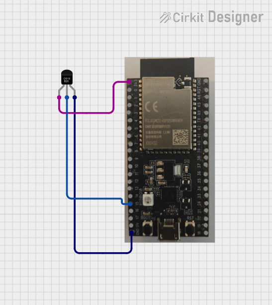
Usage Instructions
How to Use the Component in a Circuit
Powering the Board:
- Use a USB cable to power the board via the micro-USB port (5V input).
- Alternatively, connect a 7-12V power source to the VIN pin.
Connecting to Wi-Fi:
- Use the built-in Wi-Fi module to connect to a wireless network.
- Ensure the correct SSID and password are configured in your code.
Programming the Board:
- Install the ESP32 board package in the Arduino IDE or use the ESP-IDF framework.
- Connect the board to your computer via USB and select the correct COM port.
Using GPIO Pins:
- Configure GPIO pins as input or output in your code.
- Use pull-up or pull-down resistors as needed for stable operation.
Important Considerations and Best Practices
- Voltage Levels: Ensure all connected components operate at 3.3V logic levels to avoid damaging the board.
- Deep Sleep Mode: Use deep sleep mode to conserve power in battery-powered applications.
- Pin Multiplexing: Some pins have multiple functions (e.g., ADC, PWM, UART). Check the datasheet to avoid conflicts.
- External Antenna: For better Wi-Fi performance, consider using an external antenna if supported.
Example Code for Arduino UNO
Below is an example of how to connect the FREENOVE ESP32 WROVER E to Wi-Fi and blink an LED:
#include <WiFi.h> // Include the Wi-Fi library

// Replace with your network credentials
const char* ssid = "Your_SSID";
const char* password = "Your_PASSWORD";

const int ledPin = 2; // GPIO2 is connected to the onboard LED

void setup() {
  Serial.begin(115200); // Start serial communication
  pinMode(ledPin, OUTPUT); // Set GPIO2 as an output pin

  // Connect to Wi-Fi
  Serial.print("Connecting to Wi-Fi");
  WiFi.begin(ssid, password);
  while (WiFi.status() != WL_CONNECTED) {
    delay(500);
    Serial.print(".");
  }
  Serial.println("\nConnected to Wi-Fi");
}

void loop() {
  digitalWrite(ledPin, HIGH); // Turn the LED on
  delay(1000); // Wait for 1 second
  digitalWrite(ledPin, LOW); // Turn the LED off
  delay(1000); // Wait for 1 second
}
Troubleshooting and FAQs
Common Issues Users Might Face
Board Not Detected by Computer:
- Ensure the USB cable is functional and supports data transfer.
- Install the correct USB-to-serial driver for the ESP32.
Wi-Fi Connection Fails:
- Double-check the SSID and password in your code.
- Ensure the Wi-Fi network is within range and not using unsupported security protocols.
GPIO Pin Not Working:
- Verify the pin configuration in your code.
- Check for pin conflicts if the pin is multiplexed with other functions.
Program Upload Fails:
- Ensure the correct board and COM port are selected in the Arduino IDE.
- Press and hold the "BOOT" button on the board during the upload process if needed.
Solutions and Tips for Troubleshooting
- Reset the Board: Press the "EN" button to reset the board if it becomes unresponsive.
- Check Power Supply: Ensure the board is receiving sufficient power, especially when using external peripherals.
- Use Serial Monitor: Use the Serial Monitor in the Arduino IDE to debug and view error messages.
- Consult Documentation: Refer to the official FREENOVE ESP32 WROVER E datasheet for detailed technical information.