How to Use Wireless Charger Module: Examples, Pinouts, and Specs
Introduction
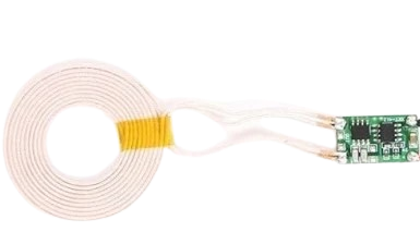
A wireless charger module is an innovative component that allows for the transfer of electrical power without the need for physical connectors or cables. It operates on the principle of electromagnetic induction, where a transmitter coil in the module creates an alternating electromagnetic field that induces a current in a receiver coil within a compatible device, thus charging its battery. Common applications include charging smartphones, smartwatches, and other portable electronic devices that support wireless charging.
Explore Projects Built with Wireless Charger Module
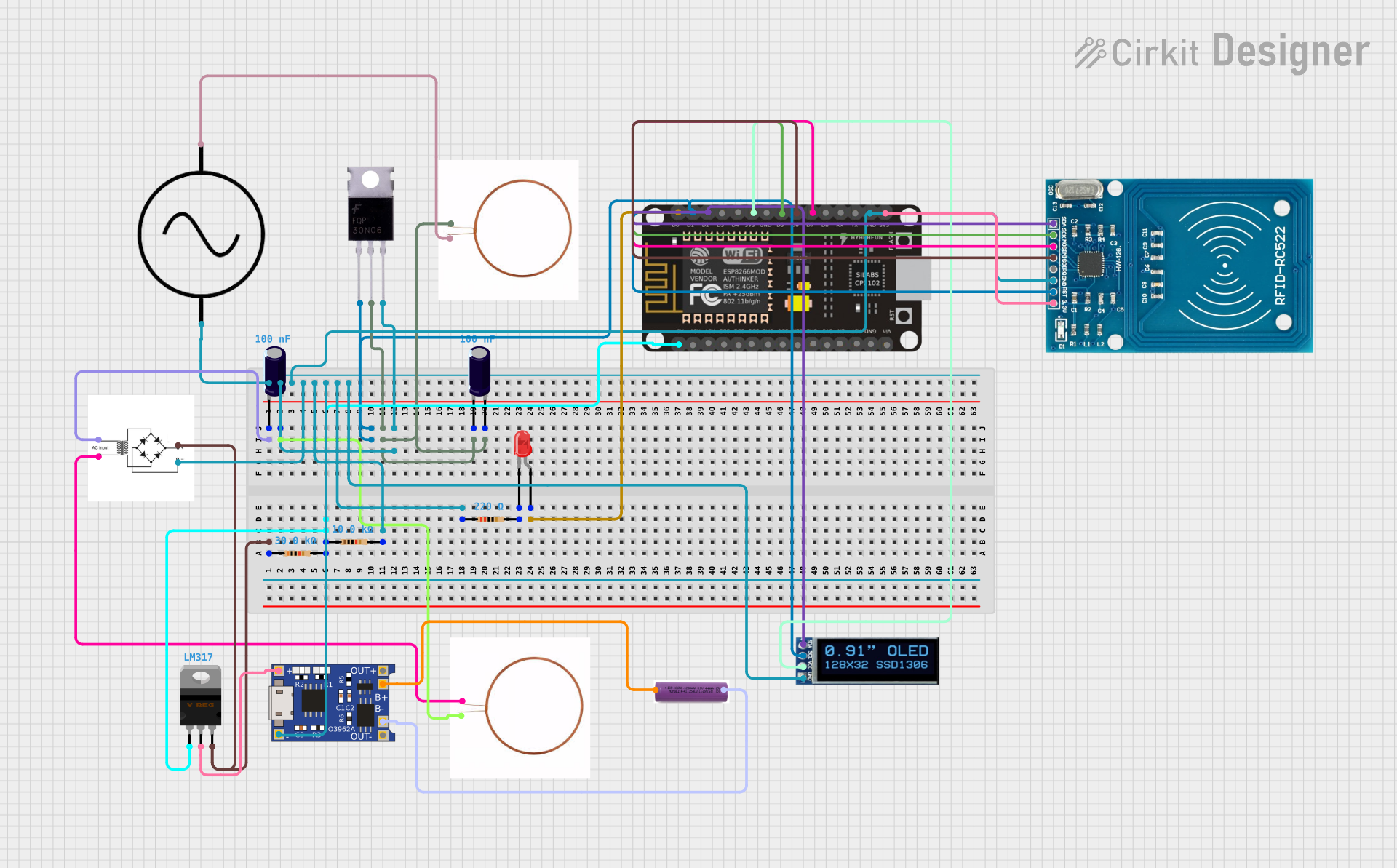

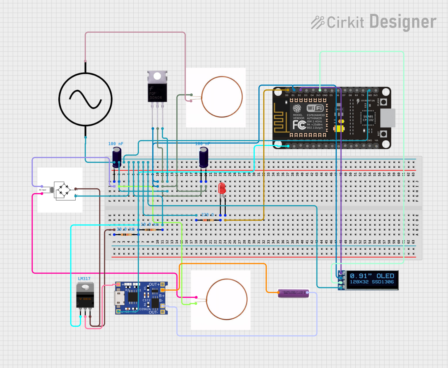

Explore Projects Built with Wireless Charger Module
Technical Specifications
General Specifications
- Operating Frequency: Typically around 100-205 kHz
- Input Voltage: 5V to 12V DC, depending on the model
- Output Voltage: 5V DC
- Charging Current: Up to 1A or more, model dependent
- Charging Efficiency: Approximately 70-85%
- Operating Distance: Up to 5mm, optimal at 2-3mm
- Operating Temperature: -10°C to +50°C
Pin Configuration and Descriptions
| Pin Number | Name | Description |
|---|---|---|
| 1 | VCC | Power supply input, typically 5V to 12V DC |
| 2 | GND | Ground connection |
| 3 | D+ | Data plus for USB communication (if applicable) |
| 4 | D- | Data minus for USB communication (if applicable) |
| 5 | ID | Identification pin for device communication (optional) |
Usage Instructions
Integration into a Circuit
- Power Supply Connection: Connect the VCC and GND pins to a suitable power supply, ensuring that the voltage and current ratings are within the module's specifications.
- Device Placement: Position the device with the receiver coil directly above the transmitter coil of the wireless charger module. The optimal distance is typically 2-3mm for efficient power transfer.
- Status Indicators: Some modules may include LED indicators to show the charging status. Refer to the module's datasheet for specific indicator behaviors.
Best Practices
- Alignment: Ensure proper alignment between the transmitter and receiver coils for maximum efficiency.
- Avoiding Obstructions: Remove any metallic objects or obstructions between the coils to prevent interference.
- Heat Management: Provide adequate ventilation around the module to dissipate heat generated during charging.
- Safety Precautions: Do not expose the module to water or other conductive liquids.
Troubleshooting and FAQs
Common Issues and Solutions
- Device Not Charging: Check the alignment of the device and the module. Ensure there are no obstructions and that the power supply is correctly connected.
- Overheating: If the module becomes too hot, reduce the charging time or improve ventilation. Check for any short circuits or overloads.
- Intermittent Charging: Ensure stable power supply and check for loose connections. Also, verify that the device's receiver coil is functioning properly.
FAQs
Q: Can the wireless charger module charge any device? A: The module can only charge devices equipped with a compatible wireless charging receiver coil and circuitry.
Q: Is it safe to leave the charger module powered on when not in use? A: Yes, but it is energy-efficient to turn it off when not charging a device.
Q: How do I know if my device is charging? A: Most wireless charger modules have an LED indicator that lights up or changes color when a device is charging.
Example Code for Arduino UNO Integration
// This example assumes the use of a wireless charger module with an Arduino UNO
// for control purposes, such as LED indication or enabling/disabling the module.

const int chargerEnablePin = 2; // Connect to the enable pin of the module if available
const int chargingStatusLED = 13; // Onboard LED used to indicate charging status

void setup() {
  pinMode(chargerEnablePin, OUTPUT);
  pinMode(chargingStatusLED, OUTPUT);

  // Enable the wireless charger module
  digitalWrite(chargerEnablePin, HIGH);
}

void loop() {
  // The actual charging process is handled by the wireless charger module hardware.
  // Here, we can simply blink an LED to indicate that the module is active.

  digitalWrite(chargingStatusLED, HIGH); // Turn on the LED
  delay(1000); // Wait for 1 second
  digitalWrite(chargingStatusLED, LOW); // Turn off the LED
  delay(1000); // Wait for 1 second
}
Note: The above code is a simple demonstration and does not interact with the wireless charging process directly. The module itself manages the charging, and the code is used for auxiliary functions such as LED control. Always refer to the specific module's datasheet for detailed information on interfacing and control features.