Cirkit Designer Logo
Cirkit Designer
Your all-in-one circuit design IDE
Home / 
Component Documentation

How to Use OPT101P: Examples, Pinouts, and Specs

Image of OPT101P
Cirkit Designer LogoDesign with OPT101P in Cirkit Designer

Introduction

The OPT101P, manufactured by Texas Instruments, is a precision optical sensor that integrates a photodiode and a transimpedance amplifier into a single package. This design simplifies light measurement applications by eliminating the need for external components to amplify the photodiode's output. The OPT101P is ideal for applications requiring accurate light intensity measurements, such as ambient light sensing, optical instrumentation, and medical devices.

Explore Projects Built with OPT101P

Use Cirkit Designer to design, explore, and prototype these projects online. Some projects support real-time simulation. Click "Open Project" to start designing instantly!
Battery-Powered Health Monitoring System with Nucleo WB55RG and OLED Display
Image of Pulsefex: A project utilizing OPT101P in a practical application
This circuit is a multi-sensor data acquisition system that uses a Nucleo WB55RG microcontroller to interface with a digital temperature sensor (TMP102), a pulse oximeter and heart-rate sensor (MAX30102), and a 0.96" OLED display via I2C. Additionally, it includes a Sim800l module for GSM communication, powered by a 3.7V LiPo battery.
Cirkit Designer LogoOpen Project in Cirkit Designer
ESP32 Mini Battery-Powered OLED Display with RTC and Potentiometer Control
Image of copy ulit nya: A project utilizing OPT101P in a practical application
This circuit is a battery-powered IoT device featuring an ESP32 microcontroller, an OLED display, and an RTC module for timekeeping. It includes a TP4056 for battery charging, a potentiometer for user input, and a pushbutton for resetting the ESP32. The circuit is designed to display information on the OLED and maintain accurate time using the RTC, with power management handled by the TP4056 and voltage regulation by the LM2596 and AMS1117.
Cirkit Designer LogoOpen Project in Cirkit Designer
Satellite-Based Timing and Navigation System with SDR and Atomic Clock Synchronization
Image of GPS 시스템 측정 구성도_Confirm: A project utilizing OPT101P in a practical application
This circuit appears to be a complex system involving power supply management, GPS and timing synchronization, and data communication. It includes a SI-TEX G1 Satellite Compass for GPS data, an XHTF1021 Atomic Rubidium Clock for precise timing, and Ettus USRP B200 units for software-defined radio communication. Power is supplied through various SMPS units and distributed via terminal blocks and DC jacks. Data communication is facilitated by Beelink MINI S12 N95 computers, RS232 splitters, and a 1000BASE-T Media Converter for network connectivity. RF Directional Couplers are used to interface antennas with the USRP units, and the entire system is likely contained within cases for protection and organization.
Cirkit Designer LogoOpen Project in Cirkit Designer
Arduino 101 and ESP32 CAM Motion-Activated Servo Control System
Image of FINAL YEAR: A project utilizing OPT101P in a practical application
This circuit features an Arduino 101 microcontroller interfaced with various components for sensing and actuation. A touch sensor and a PIR motion sensor provide input signals, which the Arduino can use to drive a micro servo, a passive buzzer, and communicate with an ESP32 CAM module for potential image capture or video streaming. The circuit also includes a red LED with a current-limiting resistor, and all components share a common power supply from the Arduino's 5V output.
Cirkit Designer LogoOpen Project in Cirkit Designer

Explore Projects Built with OPT101P

Use Cirkit Designer to design, explore, and prototype these projects online. Some projects support real-time simulation. Click "Open Project" to start designing instantly!
Image of Pulsefex: A project utilizing OPT101P in a practical application
Battery-Powered Health Monitoring System with Nucleo WB55RG and OLED Display
This circuit is a multi-sensor data acquisition system that uses a Nucleo WB55RG microcontroller to interface with a digital temperature sensor (TMP102), a pulse oximeter and heart-rate sensor (MAX30102), and a 0.96" OLED display via I2C. Additionally, it includes a Sim800l module for GSM communication, powered by a 3.7V LiPo battery.
Cirkit Designer LogoOpen Project in Cirkit Designer
Image of copy ulit nya: A project utilizing OPT101P in a practical application
ESP32 Mini Battery-Powered OLED Display with RTC and Potentiometer Control
This circuit is a battery-powered IoT device featuring an ESP32 microcontroller, an OLED display, and an RTC module for timekeeping. It includes a TP4056 for battery charging, a potentiometer for user input, and a pushbutton for resetting the ESP32. The circuit is designed to display information on the OLED and maintain accurate time using the RTC, with power management handled by the TP4056 and voltage regulation by the LM2596 and AMS1117.
Cirkit Designer LogoOpen Project in Cirkit Designer
Image of GPS 시스템 측정 구성도_Confirm: A project utilizing OPT101P in a practical application
Satellite-Based Timing and Navigation System with SDR and Atomic Clock Synchronization
This circuit appears to be a complex system involving power supply management, GPS and timing synchronization, and data communication. It includes a SI-TEX G1 Satellite Compass for GPS data, an XHTF1021 Atomic Rubidium Clock for precise timing, and Ettus USRP B200 units for software-defined radio communication. Power is supplied through various SMPS units and distributed via terminal blocks and DC jacks. Data communication is facilitated by Beelink MINI S12 N95 computers, RS232 splitters, and a 1000BASE-T Media Converter for network connectivity. RF Directional Couplers are used to interface antennas with the USRP units, and the entire system is likely contained within cases for protection and organization.
Cirkit Designer LogoOpen Project in Cirkit Designer
Image of FINAL YEAR: A project utilizing OPT101P in a practical application
Arduino 101 and ESP32 CAM Motion-Activated Servo Control System
This circuit features an Arduino 101 microcontroller interfaced with various components for sensing and actuation. A touch sensor and a PIR motion sensor provide input signals, which the Arduino can use to drive a micro servo, a passive buzzer, and communicate with an ESP32 CAM module for potential image capture or video streaming. The circuit also includes a red LED with a current-limiting resistor, and all components share a common power supply from the Arduino's 5V output.
Cirkit Designer LogoOpen Project in Cirkit Designer

Common Applications

  • Ambient light sensing in consumer electronics
  • Optical instrumentation and laboratory equipment
  • Medical devices for light-based measurements
  • Industrial automation and control systems
  • Barcode scanners and optical encoders

Technical Specifications

The OPT101P is designed for high-performance light measurement with the following key specifications:

Parameter Value
Supply Voltage (Vcc) 2.7V to 36V
Supply Current 120 µA (typical)
Output Voltage Range 0V to (Vcc - 1.2V)
Photodiode Active Area 2.29 mm²
Responsivity 0.45 V/µW/cm² at 650 nm
Bandwidth 14 kHz (typical)
Operating Temperature Range -40°C to +85°C
Package Type 8-pin DIP

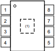
Pin Configuration and Descriptions

The OPT101P is housed in an 8-pin DIP package. The pinout and descriptions are as follows:

Pin Number Pin Name Description
1 NC No connection (leave unconnected or grounded for stability).
2 V- Negative power supply (typically connected to ground).
3 NC No connection (leave unconnected or grounded for stability).
4 OUT Output voltage proportional to light intensity.
5 NC No connection (leave unconnected or grounded for stability).
6 V+ Positive power supply (2.7V to 36V).
7 NC No connection (leave unconnected or grounded for stability).
8 PD Photodiode cathode (internally connected to the amplifier).

Usage Instructions

How to Use the OPT101P in a Circuit

  1. Power Supply: Connect the V+ pin (Pin 6) to a stable power supply within the range of 2.7V to 36V. Connect the V- pin (Pin 2) to ground.
  2. Output Connection: The output voltage is available at the OUT pin (Pin 4). This voltage is proportional to the intensity of light incident on the photodiode.
  3. Load Resistor: If required, connect a load resistor to the OUT pin to adjust the output impedance.
  4. Bypass Capacitor: Place a 0.1 µF ceramic capacitor between V+ and V- to filter noise and stabilize the power supply.
  5. Light Source: Ensure the photodiode is exposed to the light source you wish to measure. The sensor is most responsive to light in the 650 nm wavelength range.

Important Considerations and Best Practices

  • Ambient Light: Avoid exposing the sensor to excessive ambient light, as it may saturate the output.
  • Temperature Effects: The sensor's performance may vary slightly with temperature. Ensure proper thermal management in high-temperature environments.
  • Output Voltage Range: The output voltage cannot exceed (Vcc - 1.2V). Ensure your circuit design accounts for this limitation.
  • PCB Layout: Minimize noise by keeping the traces between the sensor and other components as short as possible. Use a ground plane for better noise immunity.

Example: Connecting OPT101P to an Arduino UNO

The OPT101P can be easily interfaced with an Arduino UNO for light intensity measurement. Below is an example circuit and code:

Circuit Diagram

  1. Connect Pin 6 (V+) of the OPT101P to the Arduino's 5V pin.
  2. Connect Pin 2 (V-) of the OPT101P to the Arduino's GND pin.
  3. Connect Pin 4 (OUT) of the OPT101P to the Arduino's analog input pin (e.g., A0).

Arduino Code

// OPT101P Light Sensor Example
// Reads light intensity from the OPT101P and displays it on the Serial Monitor.

const int sensorPin = A0; // Analog pin connected to OPT101P OUT pin

void setup() {
  Serial.begin(9600); // Initialize serial communication at 9600 baud
}

void loop() {
  int sensorValue = analogRead(sensorPin); // Read the analog value from the sensor
  float voltage = sensorValue * (5.0 / 1023.0); // Convert ADC value to voltage
  Serial.print("Light Intensity Voltage: ");
  Serial.print(voltage);
  Serial.println(" V");
  delay(500); // Wait for 500ms before the next reading
}

Troubleshooting and FAQs

Common Issues and Solutions

  1. No Output Voltage:

    • Ensure the power supply is connected correctly to V+ and V-.
    • Verify that the photodiode is exposed to a light source.
    • Check for loose or incorrect connections in the circuit.
  2. Output Voltage Saturation:

    • Reduce the intensity of the light source to avoid saturating the sensor.
    • Ensure the output voltage does not exceed (Vcc - 1.2V).
  3. Noisy Output:

    • Add a bypass capacitor (0.1 µF) between V+ and V- to filter noise.
    • Use shielded cables or a ground plane to minimize electromagnetic interference.
  4. Incorrect Readings with Arduino:

    • Verify that the Arduino's analog reference voltage matches the sensor's output range.
    • Check the wiring between the sensor and the Arduino.

FAQs

Q: Can the OPT101P measure infrared light?
A: Yes, the OPT101P can measure infrared light, but its peak responsivity is at 650 nm. The sensitivity decreases for wavelengths outside the visible spectrum.

Q: What is the maximum distance for light measurement?
A: The maximum distance depends on the intensity of the light source and the sensor's sensitivity. For weak light sources, the sensor should be placed closer to the source.

Q: Can I use the OPT101P with a 3.3V microcontroller?
A: Yes, the OPT101P operates with supply voltages as low as 2.7V, making it compatible with 3.3V systems.

Q: How do I protect the sensor from damage?
A: Avoid exposing the sensor to excessive light intensity or voltages beyond its specified range. Use proper filtering and shielding to protect against noise and interference.