
How to Use DOSonCHIP IC: Examples, Pinouts, and Specs
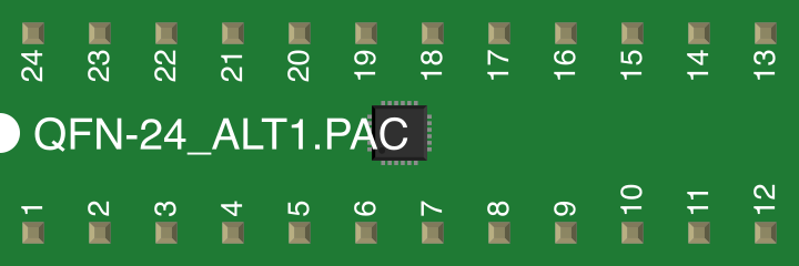
 Design with DOSonCHIP IC in Cirkit Designer
Introduction
The DOSonCHIP IC is a high-performance digital signal processing (DSP) integrated circuit designed for advanced applications in communication systems, data processing, and real-time signal analysis. Its robust architecture and versatile functionality make it a popular choice for engineers working on projects requiring efficient data manipulation and signal computation.
Explore Projects Built with DOSonCHIP IC
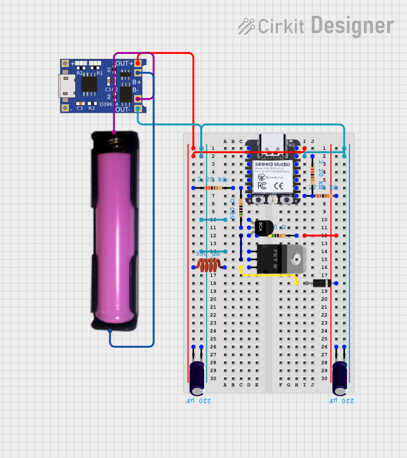 Open Project in Cirkit Designer
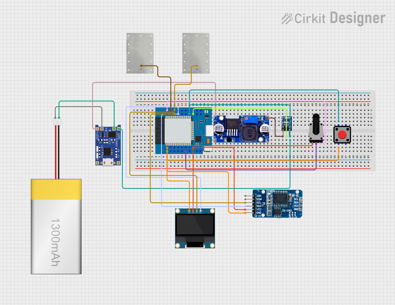 Open Project in Cirkit Designer
 Open Project in Cirkit Designer
 Open Project in Cirkit Designer
Explore Projects Built with DOSonCHIP IC
Open Project in Cirkit DesignerOpen Project in Cirkit DesignerOpen Project in Cirkit DesignerOpen Project in Cirkit DesignerCommon Applications and Use Cases
- Wireless communication systems (e.g., modulation/demodulation tasks)
- Audio and video signal processing
- Real-time data analysis in industrial automation
- High-speed data compression and decompression
- Radar and sonar signal processing
Technical Specifications
The DOSonCHIP IC is engineered to deliver exceptional performance while maintaining low power consumption. Below are its key technical specifications:
General Specifications
| Parameter | Value |
|---|---|
| Supply Voltage (Vcc) | 3.3V to 5V |
| Operating Frequency | Up to 200 MHz |
| Power Consumption | 1.2 W (typical) |
| Data Bus Width | 16-bit or 32-bit |
| Package Type | QFP-64 (Quad Flat Package) |
| Operating Temperature | -40°C to +85°C |
Pin Configuration and Descriptions
The DOSonCHIP IC features a 64-pin configuration. Below is a summary of the key pins and their functions:
| Pin Number | Pin Name | Description |
|---|---|---|
| 1 | VCC | Positive power supply (3.3V to 5V). |
| 2 | GND | Ground connection. |
| 3-10 | DATA[0:7] | 8-bit data bus for input/output operations. |
| 11-18 | ADDR[0:7] | Address bus for memory or peripheral access. |
| 19 | CLK | Clock input for synchronizing operations. |
| 20 | RESET | Active-low reset pin to initialize the IC. |
| 21-28 | IO[0:7] | General-purpose input/output pins. |
| 29 | INT | Interrupt request output. |
| 30 | CS | Chip select input for enabling the IC. |
| 31-64 | Reserved | Reserved for future use or custom configurations. |
Usage Instructions
How to Use the DOSonCHIP IC in a Circuit
- Power Supply: Connect the VCC pin to a stable 3.3V or 5V power source and the GND pin to the ground.
- Clock Signal: Provide a clock signal (up to 200 MHz) to the CLK pin for proper operation.
- Reset: Use the RESET pin to initialize the IC during power-up or when needed.
- Data and Address Buses: Connect the DATA and ADDR pins to the appropriate microcontroller or memory module for data exchange.
- Chip Select: Use the CS pin to enable or disable the IC during operation.
- Interrupt Handling: Monitor the INT pin for interrupt signals, which can be used to trigger specific actions in your system.
Important Considerations and Best Practices
- Ensure proper decoupling capacitors (e.g., 0.1 µF) are placed near the VCC and GND pins to minimize noise.
- Use a stable and precise clock source to achieve optimal performance.
- Avoid leaving unused pins floating; connect them to GND or VCC as per the datasheet recommendations.
- Follow proper PCB layout guidelines to minimize electromagnetic interference (EMI) and signal crosstalk.
Example: Connecting DOSonCHIP IC to an Arduino UNO
Below is an example of how to interface the DOSonCHIP IC with an Arduino UNO for basic data processing:
// Example: Interfacing DOSonCHIP IC with Arduino UNO
// This code demonstrates basic communication with the DOSonCHIP IC

#define DATA_BUS_START 2  // Define starting pin for data bus (D2 to D9)
#define CS_PIN 10         // Chip Select pin
#define RESET_PIN 11      // Reset pin

void setup() {
  // Initialize data bus pins as output
  for (int i = 0; i < 8; i++) {
    pinMode(DATA_BUS_START + i, OUTPUT);
  }

  // Initialize control pins
  pinMode(CS_PIN, OUTPUT);
  pinMode(RESET_PIN, OUTPUT);

  // Reset the DOSonCHIP IC
  digitalWrite(RESET_PIN, LOW);  // Activate reset
  delay(10);                     // Wait for 10ms
  digitalWrite(RESET_PIN, HIGH); // Deactivate reset

  // Enable the IC
  digitalWrite(CS_PIN, LOW);
}

void loop() {
  // Example: Send data to the DOSonCHIP IC
  byte data = 0x55;  // Example data to send
  for (int i = 0; i < 8; i++) {
    digitalWrite(DATA_BUS_START + i, (data >> i) & 0x01);
  }

  // Add your processing logic here
  delay(1000);  // Wait for 1 second before sending the next data
}
Troubleshooting and FAQs
Common Issues and Solutions
The IC does not respond to inputs.
- Verify that the power supply voltage is within the specified range (3.3V to 5V).
- Ensure the RESET pin is properly initialized during startup.
- Check the clock signal for stability and correct frequency.
Data corruption or unexpected behavior.
- Inspect the PCB layout for potential noise or interference issues.
- Use proper pull-up or pull-down resistors on unused pins as recommended.
- Confirm that the data and address buses are correctly connected.
Interrupts are not being triggered.
- Ensure the INT pin is properly connected to the microcontroller.
- Verify that the interrupt logic in your code is correctly implemented.
FAQs
Q: Can the DOSonCHIP IC operate at lower clock frequencies?
A: Yes, the IC can operate at lower frequencies, but performance may be reduced. Ensure the clock frequency is within the specified range.
Q: Is the DOSonCHIP IC compatible with 3.3V logic levels?
A: Yes, the IC is compatible with both 3.3V and 5V logic levels, making it versatile for various systems.
Q: What is the maximum data throughput of the IC?
A: The maximum data throughput depends on the clock frequency and bus width. At 200 MHz with a 32-bit bus, the IC can achieve up to 800 Mbps.
By following this documentation, users can effectively integrate and utilize the DOSonCHIP IC in their projects.