Cirkit Designer Logo
Cirkit Designer
Your all-in-one circuit design IDE
Home / 
Component Documentation

How to Use ESP 32: Examples, Pinouts, and Specs

Image of ESP 32
Cirkit Designer LogoDesign with ESP 32 in Cirkit Designer

Introduction

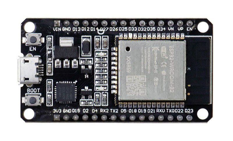
The ESP32 is a low-cost, low-power system on a chip (SoC) developed by Espressif Systems. It features integrated Wi-Fi and Bluetooth capabilities, making it an ideal choice for Internet of Things (IoT) applications, smart devices, and embedded systems. With its dual-core processor, extensive GPIO options, and support for various communication protocols, the ESP32 is a versatile and powerful component for a wide range of projects.

Explore Projects Built with ESP 32

Use Cirkit Designer to design, explore, and prototype these projects online. Some projects support real-time simulation. Click "Open Project" to start designing instantly!
ESP32-Based RF Communication System with 433 MHz Modules
Image of 433 mhz: A project utilizing ESP 32 in a practical application
This circuit comprises an ESP32 microcontroller connected to a 433 MHz RF transmitter and receiver pair. The ESP32 is programmed to receive and decode RF signals through the receiver module, as well as send RF signals via the transmitter module. Additionally, the ESP32 can communicate with a Bluetooth device to exchange commands and data, and it uses an LED for status indication.
Cirkit Designer LogoOpen Project in Cirkit Designer
ESP32-Based Environmental Monitoring System with Motion Detection
Image of pro: A project utilizing ESP 32 in a practical application
This circuit features an ESP32 microcontroller on a baseboard that interfaces with a PIR sensor for motion detection, a DHT22 sensor for measuring temperature and humidity, and a BH1750 sensor for detecting ambient light levels. The ESP32 is configured to communicate with the BH1750 using I2C protocol, with GPIO22 and GPIO21 serving as the SCL and SDA lines, respectively. Power is supplied to the sensors from the ESP32's voltage output pins, and sensor outputs are connected to designated GPIO pins for data acquisition.
Cirkit Designer LogoOpen Project in Cirkit Designer
ESP32-Based Smart Ethernet Weather Station with DHT22 Sensor and Relay Control
Image of ESP32 Single and Double AC with Temp 30Pin Micro and USBC: A project utilizing ESP 32 in a practical application
This circuit features an ESP32 microcontroller interfaced with a W5500 Ethernet module, a DHT22 temperature and humidity sensor, and a 2-channel relay module. The ESP32 is configured to communicate with the W5500 module via SPI for network connectivity, read sensor data from the DHT22, and control devices through the relay module. The purpose of this circuit is likely for environmental monitoring and control over a network.
Cirkit Designer LogoOpen Project in Cirkit Designer
ESP32-Based Sensor Monitoring System with OLED Display and E-Stop
Image of MVP_design: A project utilizing ESP 32 in a practical application
This circuit features an ESP32 microcontroller that interfaces with a variety of sensors and output devices. It is powered by a Lipo battery through a buck converter, ensuring a stable voltage supply. The ESP32 collects data from a DHT11 temperature and humidity sensor and a vibration sensor, controls a buzzer, and displays information on an OLED screen. An emergency stop (E Stop) is connected for safety purposes, allowing the system to be quickly deactivated.
Cirkit Designer LogoOpen Project in Cirkit Designer

Explore Projects Built with ESP 32

Use Cirkit Designer to design, explore, and prototype these projects online. Some projects support real-time simulation. Click "Open Project" to start designing instantly!
Image of 433 mhz: A project utilizing ESP 32 in a practical application
ESP32-Based RF Communication System with 433 MHz Modules
This circuit comprises an ESP32 microcontroller connected to a 433 MHz RF transmitter and receiver pair. The ESP32 is programmed to receive and decode RF signals through the receiver module, as well as send RF signals via the transmitter module. Additionally, the ESP32 can communicate with a Bluetooth device to exchange commands and data, and it uses an LED for status indication.
Cirkit Designer LogoOpen Project in Cirkit Designer
Image of pro: A project utilizing ESP 32 in a practical application
ESP32-Based Environmental Monitoring System with Motion Detection
This circuit features an ESP32 microcontroller on a baseboard that interfaces with a PIR sensor for motion detection, a DHT22 sensor for measuring temperature and humidity, and a BH1750 sensor for detecting ambient light levels. The ESP32 is configured to communicate with the BH1750 using I2C protocol, with GPIO22 and GPIO21 serving as the SCL and SDA lines, respectively. Power is supplied to the sensors from the ESP32's voltage output pins, and sensor outputs are connected to designated GPIO pins for data acquisition.
Cirkit Designer LogoOpen Project in Cirkit Designer
Image of ESP32 Single and Double AC with Temp 30Pin Micro and USBC: A project utilizing ESP 32 in a practical application
ESP32-Based Smart Ethernet Weather Station with DHT22 Sensor and Relay Control
This circuit features an ESP32 microcontroller interfaced with a W5500 Ethernet module, a DHT22 temperature and humidity sensor, and a 2-channel relay module. The ESP32 is configured to communicate with the W5500 module via SPI for network connectivity, read sensor data from the DHT22, and control devices through the relay module. The purpose of this circuit is likely for environmental monitoring and control over a network.
Cirkit Designer LogoOpen Project in Cirkit Designer
Image of MVP_design: A project utilizing ESP 32 in a practical application
ESP32-Based Sensor Monitoring System with OLED Display and E-Stop
This circuit features an ESP32 microcontroller that interfaces with a variety of sensors and output devices. It is powered by a Lipo battery through a buck converter, ensuring a stable voltage supply. The ESP32 collects data from a DHT11 temperature and humidity sensor and a vibration sensor, controls a buzzer, and displays information on an OLED screen. An emergency stop (E Stop) is connected for safety purposes, allowing the system to be quickly deactivated.
Cirkit Designer LogoOpen Project in Cirkit Designer

Common Applications and Use Cases

  • IoT devices (e.g., smart home automation, environmental monitoring)
  • Wireless communication systems
  • Wearable technology
  • Robotics and drones
  • Data logging and remote sensing
  • Prototyping and educational projects

Technical Specifications

The ESP32 is packed with features that make it suitable for a variety of applications. Below are its key technical specifications:

General Specifications

  • Processor: Dual-core Xtensa® 32-bit LX6 microprocessor
  • Clock Speed: Up to 240 MHz
  • RAM: 520 KB SRAM
  • Flash Memory: Typically 4 MB (varies by module)
  • Wi-Fi: 802.11 b/g/n
  • Bluetooth: v4.2 BR/EDR and BLE
  • Operating Voltage: 3.3V
  • GPIO Pins: 34 (multipurpose, including ADC, DAC, PWM, I2C, SPI, UART)

Pin Configuration and Descriptions

The ESP32 has multiple GPIO pins, each capable of serving different functions. Below is a table summarizing the key pins and their descriptions:

Pin Name Function Description
GPIO0 Input/Output, Boot Mode Selection Used for boot mode selection during startup.
GPIO2 Input/Output, ADC, DAC General-purpose pin, supports ADC and DAC functions.
GPIO12 Input/Output, ADC, Touch Sensor Can be used as an ADC input or capacitive touch sensor.
GPIO13 Input/Output, PWM, Touch Sensor Supports PWM and capacitive touch sensing.
GPIO21 Input/Output, I2C SDA Default I2C data line (SDA).
GPIO22 Input/Output, I2C SCL Default I2C clock line (SCL).
GPIO23 Input/Output, SPI MOSI SPI Master Out Slave In (MOSI) line.
GPIO25 Input/Output, DAC, ADC Can be used as a DAC output or ADC input.
EN Enable Active-high pin to enable the chip.
3V3 Power Provides 3.3V power output.
GND Ground Ground connection.

Note: Not all GPIO pins are available for general use, as some are reserved for internal functions. Refer to the ESP32 datasheet for detailed pin mappings.

Usage Instructions

The ESP32 can be used in a variety of circuits and applications. Below are the steps and best practices for using the ESP32 in your projects.

Basic Setup

  1. Powering the ESP32:

    • The ESP32 operates at 3.3V. Ensure your power supply provides a stable 3.3V to avoid damaging the chip.
    • If using a development board (e.g., ESP32 DevKit), you can power it via the USB port or the 3.3V pin.
  2. Connecting to a Computer:

    • Use a micro-USB cable to connect the ESP32 development board to your computer.
    • Install the necessary USB-to-serial drivers (e.g., CP2102 or CH340) if required.
  3. Programming the ESP32:

    • Install the Arduino IDE and add the ESP32 board support package via the Board Manager.
    • Select the appropriate ESP32 board and COM port in the Arduino IDE.

Example: Blinking an LED

The following example demonstrates how to blink an LED connected to GPIO2 of the ESP32.

// Example: Blink an LED using ESP32
// Connect an LED to GPIO2 with a current-limiting resistor.

#define LED_PIN 2  // Define the GPIO pin connected to the LED

void setup() {
  pinMode(LED_PIN, OUTPUT);  // Set GPIO2 as an output pin
}

void loop() {
  digitalWrite(LED_PIN, HIGH);  // Turn the LED on
  delay(1000);                  // Wait for 1 second
  digitalWrite(LED_PIN, LOW);   // Turn the LED off
  delay(1000);                  // Wait for 1 second
}

Important Considerations

  • Voltage Levels: The ESP32 operates at 3.3V logic levels. Avoid connecting 5V signals directly to its GPIO pins.
  • Boot Mode: Ensure GPIO0 is not pulled low during normal operation, as this will put the ESP32 into bootloader mode.
  • Power Supply: Use a stable power source to prevent unexpected resets or malfunctions.

Troubleshooting and FAQs

Common Issues

  1. ESP32 Not Detected by Computer:

    • Ensure the USB cable is functional and supports data transfer.
    • Install the correct USB-to-serial driver for your development board.
  2. Program Upload Fails:

    • Check that the correct board and COM port are selected in the Arduino IDE.
    • Press and hold the "BOOT" button on the ESP32 board while uploading the code.
  3. Wi-Fi Connection Issues:

    • Verify the SSID and password in your code.
    • Ensure the Wi-Fi network is within range and operational.
  4. Random Resets:

    • Check the power supply for stability.
    • Avoid using GPIO pins that are reserved for internal functions.

FAQs

Q: Can the ESP32 be powered with 5V?
A: The ESP32 itself operates at 3.3V, but many development boards include a voltage regulator that allows them to be powered with 5V via the USB port or VIN pin.

Q: How do I use the Bluetooth functionality?
A: The ESP32 supports both Bluetooth Classic and BLE. You can use the Arduino IDE or ESP-IDF to program Bluetooth functionality. Libraries such as BluetoothSerial and BLEDevice are available for easy implementation.

Q: Can I use the ESP32 with sensors and modules?
A: Yes, the ESP32 supports a wide range of sensors and modules via I2C, SPI, UART, and analog inputs. Ensure proper voltage compatibility when connecting external components.

By following this documentation, you can effectively use the ESP32 in your projects and troubleshoot common issues. For advanced features, refer to the official ESP32 datasheet and programming guides.