How to Use RS485 Shield on Arduino Leonardo: Examples, Pinouts, and Specs

Introduction
The RS485 Shield for Arduino Leonardo is an expansion board that enables the Arduino Leonardo microcontroller to communicate using the RS485 protocol. This protocol is widely used in industrial automation, building automation, and other applications that require robust communication over long distances or in electrically noisy environments.
Explore Projects Built with RS485 Shield on Arduino Leonardo
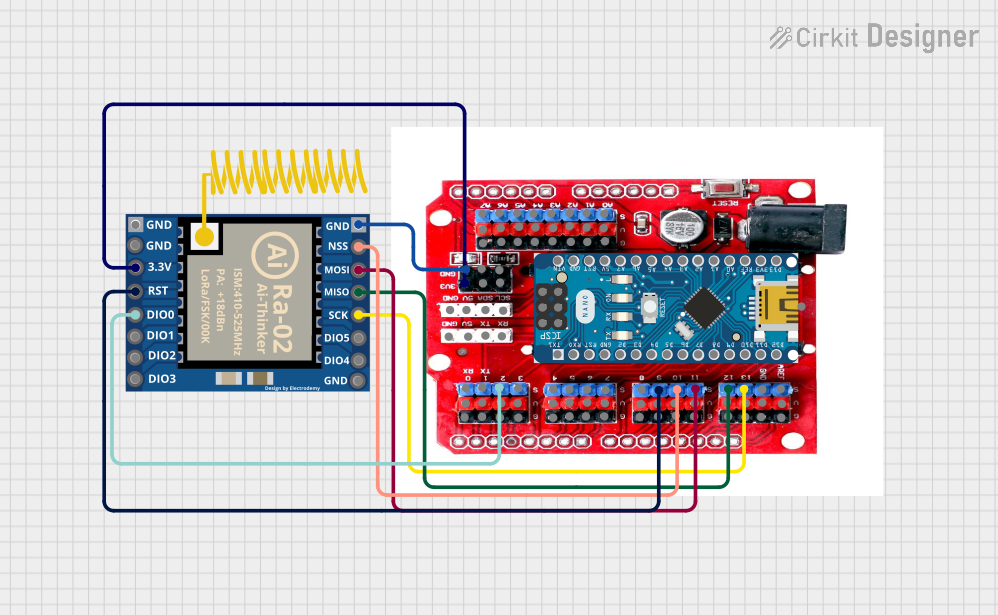
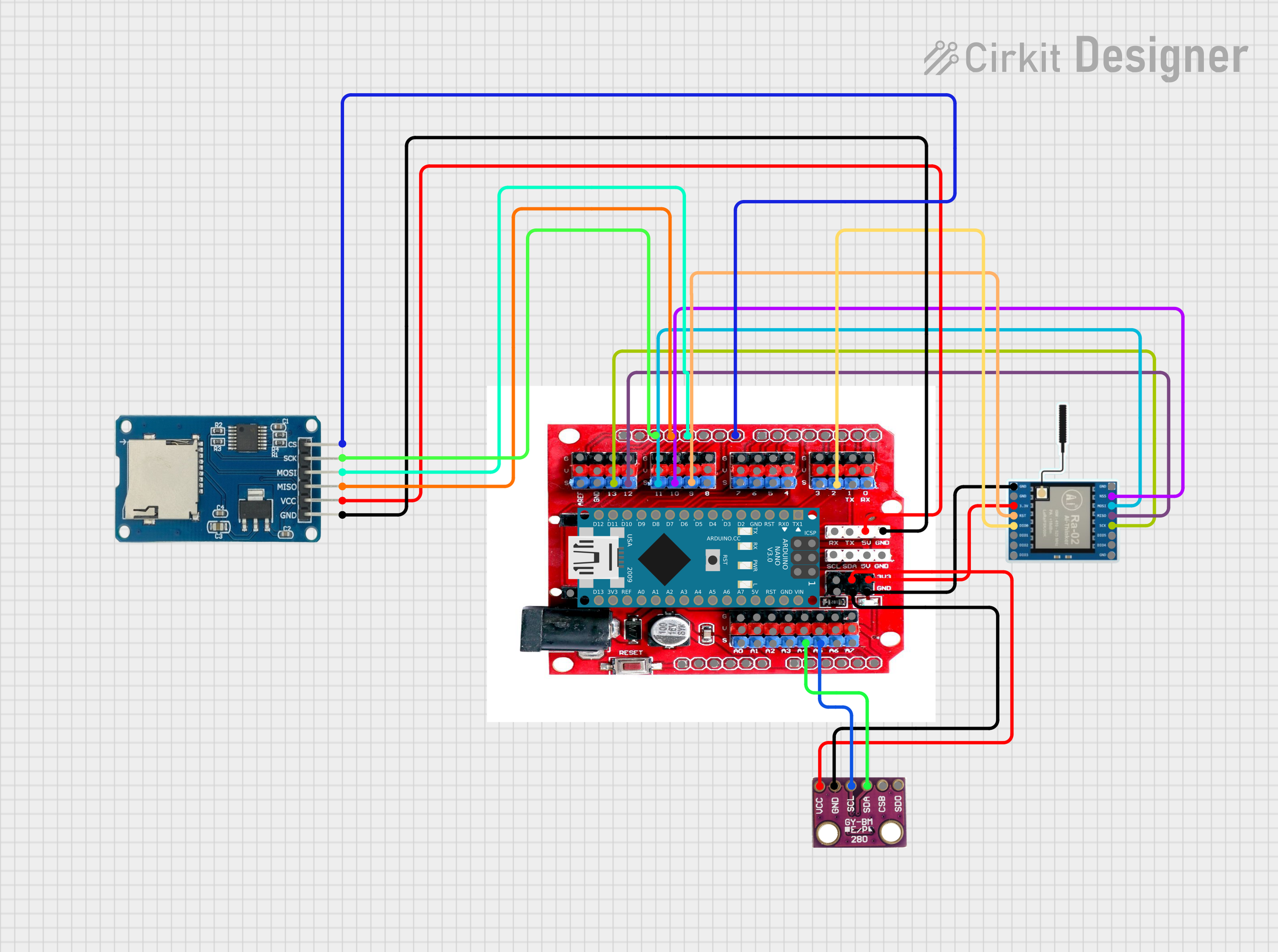
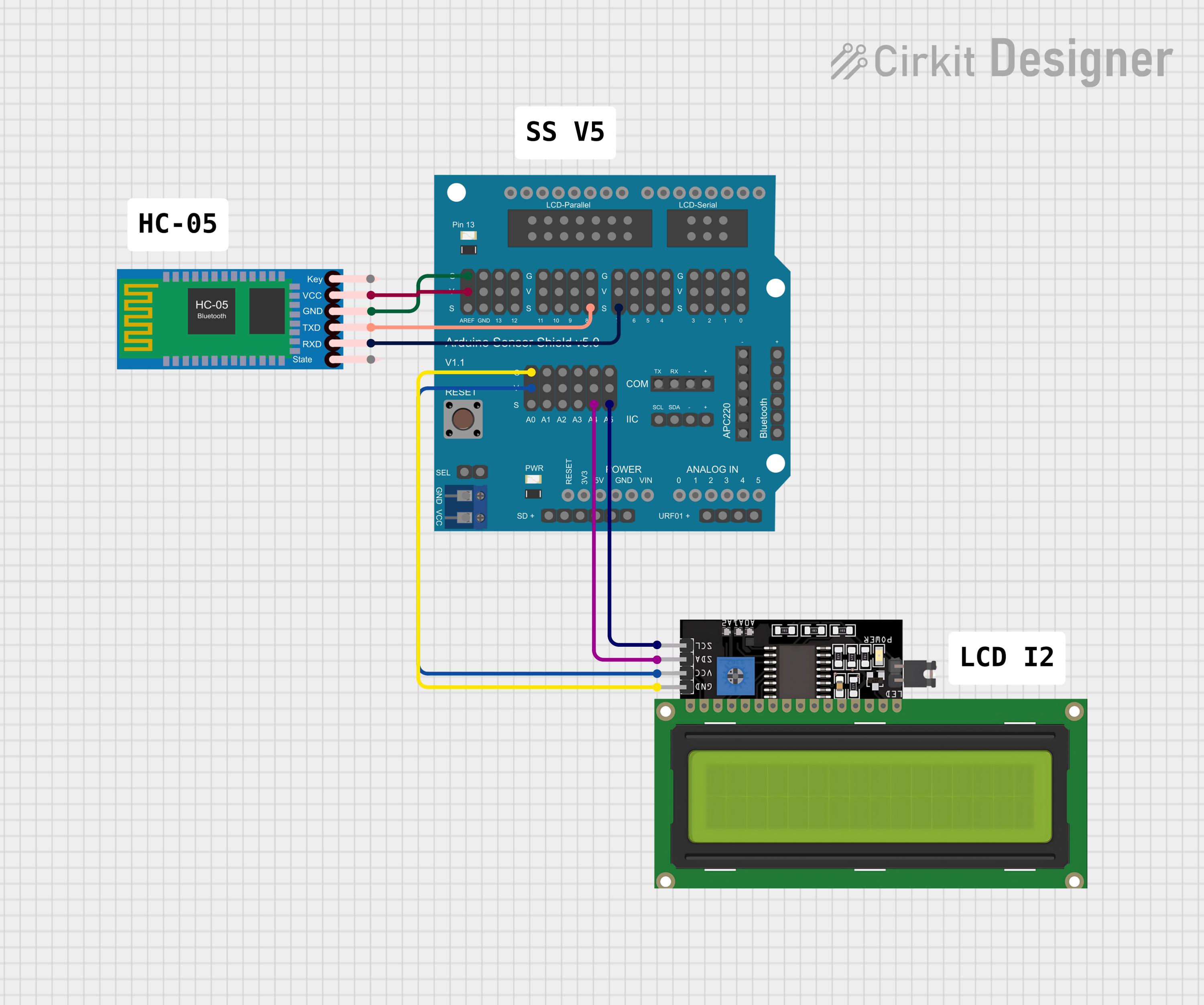

Explore Projects Built with RS485 Shield on Arduino Leonardo
Common Applications and Use Cases
- Industrial control systems
- Building management systems
- Distributed control systems
- Networked communication between multiple microcontrollers
Technical Specifications
Key Technical Details
- Operating Voltage: 5V (supplied by the Arduino Leonardo)
- Baud Rate: Up to 10 Mbps
- Maximum Cable Length: 1200 meters (4000 feet)
- Differential Signaling: Balanced transmission for noise immunity
Pin Configuration and Descriptions
| Pin Number | Function | Description |
|---|---|---|
| 1 | RO (Receiver Output) | Connects to the Arduino's RX pin for data reception. |
| 2 | RE (Receiver Enable) | Enables the receiver when LOW. |
| 3 | DE (Driver Enable) | Enables the driver when HIGH. |
| 4 | DI (Driver Input) | Connects to the Arduino's TX pin for data transmission. |
| 5 | VCC | Power supply for the RS485 transceiver (5V). |
| 6 | GND | Ground connection. |
| 7 | A | Non-inverting receiver and driver output. |
| 8 | B | Inverting receiver and driver output. |
Usage Instructions
How to Use the Component in a Circuit
- Mount the Shield: Carefully align the RS485 Shield pins with the headers on the Arduino Leonardo and press down to seat the shield.
- Connect the RS485 Network: Attach the A and B lines of your RS485 network to the respective A and B terminals on the shield.
- Power the System: Ensure that the Arduino Leonardo is powered through its USB connection or an external power supply.
Important Considerations and Best Practices
- Termination Resistors: Use termination resistors at both ends of the RS485 network to prevent signal reflections.
- Biasing Resistors: Ensure proper biasing of the RS485 lines to maintain signal integrity.
- Cable Quality: Use twisted-pair cables for the A and B lines to enhance noise immunity.
- Grounding: Connect the ground of the RS485 network to the GND pin on the shield to avoid potential differences.
Example Code for Arduino Leonardo
#include <SoftwareSerial.h>

// Configure the RS485 control pins
const int RE_DE = 2; // Example pin for controlling RE and DE

// Initialize the RS485 transceiver state
void setupRS485Transceiver() {
  pinMode(RE_DE, OUTPUT);
  digitalWrite(RE_DE, LOW); // Enable Receiver by default
}

// Function to send data over RS485
void sendRS485Data(const char *data) {
  digitalWrite(RE_DE, HIGH); // Enable Driver
  Serial1.write(data); // Send data
  Serial1.flush(); // Ensure all data is transmitted
  digitalWrite(RE_DE, LOW); // Disable Driver, Enable Receiver
}

// Setup function
void setup() {
  Serial1.begin(9600); // Start serial communication at 9600 baud
  setupRS485Transceiver();
}

// Main loop
void loop() {
  // Example data to send
  const char *testData = "Hello RS485";
  sendRS485Data(testData);
  delay(1000); // Wait for a second
}
Troubleshooting and FAQs
Common Issues Users Might Face
- No Data Transmission: Ensure that the RE and DE pins are correctly controlled and that the shield is properly seated on the Arduino Leonardo.
- Garbled Data: Check for proper termination and biasing resistors, and verify that the baud rate matches on all devices in the RS485 network.
- Short Range: Ensure that high-quality twisted-pair cables are used and that the cable length does not exceed the maximum specified distance.
Solutions and Tips for Troubleshooting
- Check Connections: Verify all connections, including power to the shield and the A and B line connections.
- Baud Rate Configuration: Ensure that the baud rate is correctly set in the software and matches across all devices.
- Use of Libraries: Consider using an RS485 library to simplify the code and ensure proper timing and control of the transceiver.
FAQs
Q: Can I use the RS485 Shield with other Arduino boards?
A: While this shield is designed for the Arduino Leonardo, it may be compatible with other Arduino boards that share the same pinout for the key communication pins. However, you may need to adjust the code accordingly.
Q: How many devices can I connect to an RS485 network?
A: The RS485 protocol allows for up to 32 devices on a single bus without repeaters. With repeaters, you can extend this number significantly.
Q: Do I need to use both A and B lines for communication?
A: Yes, RS485 communication requires both A (non-inverting) and B (inverting) lines for differential signaling, which provides noise immunity.