Cirkit Designer Logo
Cirkit Designer
Your all-in-one circuit design IDE
Home / 
Component Documentation

How to Use Adafruit HUZZAH ESP8266: Examples, Pinouts, and Specs

Image of Adafruit HUZZAH ESP8266
Cirkit Designer LogoDesign with Adafruit HUZZAH ESP8266 in Cirkit Designer

Introduction

The Adafruit HUZZAH ESP8266 is a versatile WiFi development board that harnesses the capabilities of the ESP8266 module, a popular and cost-effective WiFi-microcontroller chip. This board is designed for Internet of Things (IoT) projects and applications that require wireless internet connectivity. It is widely used for home automation, sensor networks, and DIY electronics projects due to its ease of use and extensive community support.

Explore Projects Built with Adafruit HUZZAH ESP8266

Use Cirkit Designer to design, explore, and prototype these projects online. Some projects support real-time simulation. Click "Open Project" to start designing instantly!
Battery-Powered ESP32 Temperature Monitoring System
Image of Temp Sensor: A project utilizing Adafruit HUZZAH ESP8266 in a practical application
This circuit consists of an Adafruit HUZZAH32 ESP32 Feather microcontroller, a temperature sensor, and a battery. The ESP32 reads temperature data from the sensor and is powered by the battery, enabling wireless temperature monitoring.
Cirkit Designer LogoOpen Project in Cirkit Designer
Arduino and ESP8266 Wi-Fi Interactive Control Panel
Image of Circuit schematic: A project utilizing Adafruit HUZZAH ESP8266 in a practical application
This circuit features an Arduino UNO and an Adafruit Feather HUZZAH ESP8266 microcontroller, which are interconnected for serial communication. The Arduino is also connected to a 16x2 I2C LCD for display, a servo motor, a piezo buzzer, an LED with a resistor, and a 4x4 membrane matrix keypad for user input. The purpose of the circuit is likely to involve user interaction through the keypad, feedback through the LCD, LED, and buzzer, and control of the servo motor, with potential WiFi capabilities provided by the ESP8266.
Cirkit Designer LogoOpen Project in Cirkit Designer
ESP8266 WiFi Module Serial Interface with Pushbutton Control
Image of esp01 progrmmer: A project utilizing Adafruit HUZZAH ESP8266 in a practical application
This circuit features an ESP8266 ESP-01 WiFi module interfaced with an Adafruit FTDI Friend for serial communication. The ESP8266's TXD and RXD pins are connected to the FTDI's RX and TX pins respectively, allowing for data exchange between the microcontroller and a computer. Additionally, a pushbutton is connected to the ESP8266's reset pin, enabling manual resets of the module.
Cirkit Designer LogoOpen Project in Cirkit Designer
ESP8266-Based Multi-Sensor Monitoring System with Alert and Actuator Control
Image of wi-fi home: A project utilizing Adafruit HUZZAH ESP8266 in a practical application
This circuit features an ESP8266 microcontroller connected to various sensors and actuators. It includes an ultrasonic sensor for distance measurement, a DHT11 sensor for temperature and humidity readings, an IR flame sensor for fire detection, a buzzer for audible alerts, a bulb and a DC motor as output devices. The ESP8266 controls these components, likely to monitor and respond to environmental conditions.
Cirkit Designer LogoOpen Project in Cirkit Designer

Explore Projects Built with Adafruit HUZZAH ESP8266

Use Cirkit Designer to design, explore, and prototype these projects online. Some projects support real-time simulation. Click "Open Project" to start designing instantly!
Image of Temp Sensor: A project utilizing Adafruit HUZZAH ESP8266 in a practical application
Battery-Powered ESP32 Temperature Monitoring System
This circuit consists of an Adafruit HUZZAH32 ESP32 Feather microcontroller, a temperature sensor, and a battery. The ESP32 reads temperature data from the sensor and is powered by the battery, enabling wireless temperature monitoring.
Cirkit Designer LogoOpen Project in Cirkit Designer
Image of Circuit schematic: A project utilizing Adafruit HUZZAH ESP8266 in a practical application
Arduino and ESP8266 Wi-Fi Interactive Control Panel
This circuit features an Arduino UNO and an Adafruit Feather HUZZAH ESP8266 microcontroller, which are interconnected for serial communication. The Arduino is also connected to a 16x2 I2C LCD for display, a servo motor, a piezo buzzer, an LED with a resistor, and a 4x4 membrane matrix keypad for user input. The purpose of the circuit is likely to involve user interaction through the keypad, feedback through the LCD, LED, and buzzer, and control of the servo motor, with potential WiFi capabilities provided by the ESP8266.
Cirkit Designer LogoOpen Project in Cirkit Designer
Image of esp01 progrmmer: A project utilizing Adafruit HUZZAH ESP8266 in a practical application
ESP8266 WiFi Module Serial Interface with Pushbutton Control
This circuit features an ESP8266 ESP-01 WiFi module interfaced with an Adafruit FTDI Friend for serial communication. The ESP8266's TXD and RXD pins are connected to the FTDI's RX and TX pins respectively, allowing for data exchange between the microcontroller and a computer. Additionally, a pushbutton is connected to the ESP8266's reset pin, enabling manual resets of the module.
Cirkit Designer LogoOpen Project in Cirkit Designer
Image of wi-fi home: A project utilizing Adafruit HUZZAH ESP8266 in a practical application
ESP8266-Based Multi-Sensor Monitoring System with Alert and Actuator Control
This circuit features an ESP8266 microcontroller connected to various sensors and actuators. It includes an ultrasonic sensor for distance measurement, a DHT11 sensor for temperature and humidity readings, an IR flame sensor for fire detection, a buzzer for audible alerts, a bulb and a DC motor as output devices. The ESP8266 controls these components, likely to monitor and respond to environmental conditions.
Cirkit Designer LogoOpen Project in Cirkit Designer

Technical Specifications

Key Technical Details

  • Microcontroller: ESP8266 80MHz microcontroller
  • Operating Voltage: 3.3V
  • Input Voltage: 4-6V (for the onboard regulator) or 3.3V if bypassing the regulator
  • Digital I/O Pins: 11, all of which can do PWM, I2C, and 1-wire
  • Analog Input Pins: 1 (Analog Input is 1.0V max)
  • Flash Memory: 4MB
  • WiFi Standards: 802.11 b/g/n
  • WiFi Security: WEP, WPA/WPA2 PSK/Enterprise
  • Integrated TCP/IP protocol stack

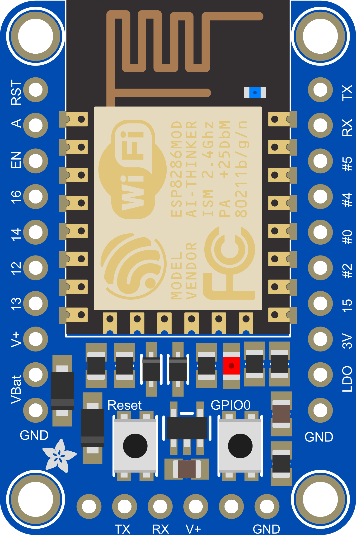
Pin Configuration and Descriptions

Pin Number Name Description
1 GND Ground
2 V+ 4-6V Input or 3.3V if bypassing the regulator
3 EN Chip Enable. Keep high (3.3V) to run.
4 RST Reset pin. Pull low to reset the chip.
5 GPIO0 General Purpose I/O and Programming Mode Select
6 GPIO2 General Purpose I/O
7 GPIO15 General Purpose I/O and Boot Mode Select
8 RX UART Receive Pin
9 TX UART Transmit Pin
10 GPIO13 General Purpose I/O
11 GPIO12 General Purpose I/O
12 GPIO14 General Purpose I/O
13 A0 Analog Input (1.0V max)

Usage Instructions

Integrating with a Circuit

To use the Adafruit HUZZAH ESP8266 in a circuit:

  1. Powering the Board: Connect a 4-6V power supply to the V+ and GND pins, or provide 3.3V directly if bypassing the onboard regulator.
  2. Programming: Connect the board to your computer using a USB-to-Serial converter to the RX and TX pins. GPIO0 must be grounded to enable the programming mode.
  3. Connecting to WiFi: Use the ESP8266's WiFi capabilities to connect to a network for internet access or to create a local server.

Important Considerations and Best Practices

  • Always ensure that the power supply is within the specified range to prevent damage.
  • Use a logic level converter if you need to interface the 3.3V logic of the ESP8266 with 5V devices.
  • When programming, ensure that GPIO0 is grounded to enable the flash mode.
  • Avoid applying more than 1.0V to the analog input to prevent damage to the ADC.

Example Code for Arduino UNO

Here is a simple example of how to connect the Adafruit HUZZAH ESP8266 to an Arduino UNO and blink an LED using the Arduino IDE:

// Define the LED pin
const int LED_PIN = 13;

void setup() {
  // Initialize the LED pin as an output
  pinMode(LED_PIN, OUTPUT);
}

void loop() {
  // Turn the LED on
  digitalWrite(LED_PIN, HIGH);
  // Wait for a second
  delay(1000);
  // Turn the LED off
  digitalWrite(LED_PIN, LOW);
  // Wait for a second
  delay(1000);
}

Note: This code is for demonstration purposes and assumes that you have already set up the ESP8266 environment in the Arduino IDE.

Troubleshooting and FAQs

Common Issues

  • Board not responding: Ensure that the board is powered correctly and that the serial connection is properly established.
  • Cannot connect to WiFi: Verify the network credentials and signal strength. Ensure the antenna is not obstructed.
  • Failure to upload sketches: Check that GPIO0 is grounded and the board is in programming mode.

Solutions and Tips

  • Board Reset: If the board becomes unresponsive, try resetting it by pulling the RST pin low.
  • Serial Monitor: Use the serial monitor in the Arduino IDE to debug and monitor the WiFi connection process.
  • Firmware Update: Periodically check for firmware updates to ensure the board has the latest features and security patches.

FAQs

Q: Can I power the Adafruit HUZZAH ESP8266 with a 5V power supply? A: Yes, you can use a 4-6V power supply, but it's recommended to use a stable 3.3V supply if bypassing the onboard regulator.

Q: How do I put the board in programming mode? A: Ground GPIO0 and reset the board to enter programming mode.

Q: Can I use the Arduino IDE to program the HUZZAH ESP8266? A: Yes, you can use the Arduino IDE with the appropriate board manager installed for ESP8266.

Q: What is the maximum voltage for the analog input? A: The maximum voltage for the analog input is 1.0V. Applying more can damage the ADC.

For further assistance, consult the Adafruit forums or the extensive online community resources dedicated to the ESP8266.