
How to Use Raspberry Pi A: Examples, Pinouts, and Specs
 Design with Raspberry Pi A in Cirkit Designer
Introduction
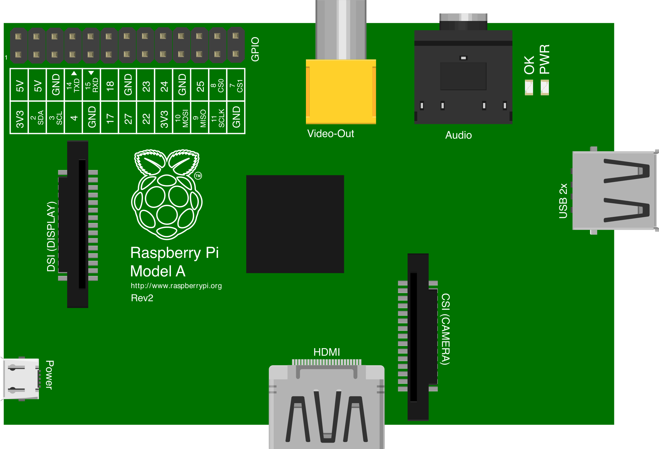
The Raspberry Pi Model A, manufactured by Raspberry Pi Ltd, is a compact and affordable single-board computer designed for educational purposes, prototyping, and hobbyist projects. It is equipped with General Purpose Input/Output (GPIO) pins for hardware interfacing and supports a variety of operating systems, including Linux-based distributions. Its small form factor and low power consumption make it ideal for embedded systems, IoT applications, and portable projects.
Explore Projects Built with Raspberry Pi A
 Open Project in Cirkit Designer
 Open Project in Cirkit Designer
 Open Project in Cirkit Designer
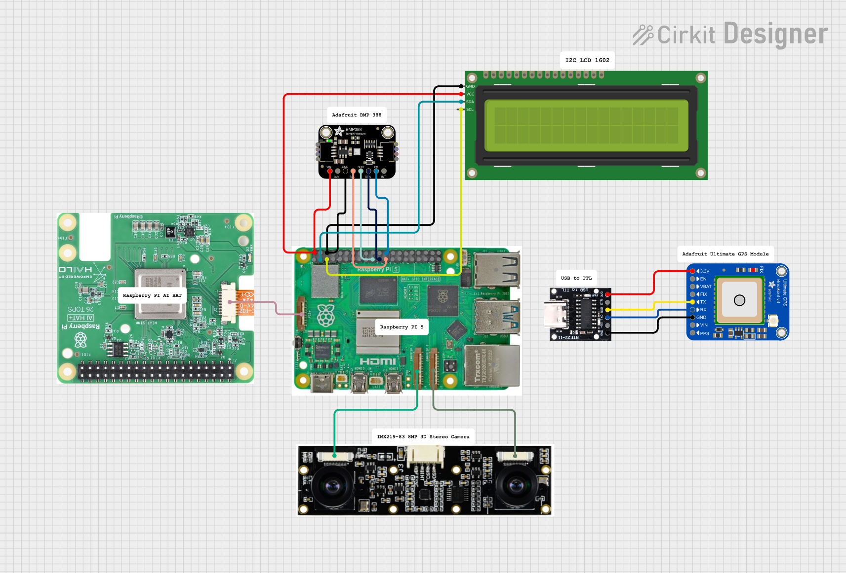 Open Project in Cirkit Designer
Explore Projects Built with Raspberry Pi A
Open Project in Cirkit DesignerOpen Project in Cirkit DesignerOpen Project in Cirkit DesignerOpen Project in Cirkit DesignerCommon Applications and Use Cases
- Educational tools for learning programming and electronics
- DIY projects such as home automation and robotics
- Media centers and lightweight servers
- IoT (Internet of Things) devices
- Prototyping hardware and software solutions
Technical Specifications
Below are the key technical details of the Raspberry Pi Model A:
| Specification | Details |
|---|---|
| Processor | Broadcom BCM2835 ARM11, 700 MHz |
| RAM | 256 MB LPDDR2 SDRAM |
| Storage | SD card slot for operating system and data storage |
| GPIO Pins | 26-pin GPIO header |
| USB Ports | 1 x USB 2.0 port |
| Video Output | HDMI and composite video |
| Audio Output | 3.5mm audio jack and HDMI |
| Networking | No onboard Ethernet or Wi-Fi |
| Power Supply | 5V micro-USB, 700mA minimum |
| Dimensions | 85.6mm x 56.5mm x 17mm |
| Weight | 23g |
GPIO Pin Configuration
The Raspberry Pi Model A features a 26-pin GPIO header. Below is the pinout configuration:
| Pin Number | Pin Name | Description |
|---|---|---|
| 1 | 3.3V Power | 3.3V power supply |
| 2 | 5V Power | 5V power supply |
| 3 | GPIO 2 (SDA1) | I2C Data |
| 4 | 5V Power | 5V power supply |
| 5 | GPIO 3 (SCL1) | I2C Clock |
| 6 | Ground | Ground |
| 7 | GPIO 4 | General-purpose I/O |
| 8 | GPIO 14 (TXD) | UART Transmit |
| 9 | Ground | Ground |
| 10 | GPIO 15 (RXD) | UART Receive |
| 11 | GPIO 17 | General-purpose I/O |
| 12 | GPIO 18 | PWM capable |
| 13 | GPIO 27 | General-purpose I/O |
| 14 | Ground | Ground |
| 15 | GPIO 22 | General-purpose I/O |
| 16 | GPIO 23 | General-purpose I/O |
| 17 | 3.3V Power | 3.3V power supply |
| 18 | GPIO 24 | General-purpose I/O |
| 19 | GPIO 10 (MOSI) | SPI Master Out, Slave In |
| 20 | Ground | Ground |
| 21 | GPIO 9 (MISO) | SPI Master In, Slave Out |
| 22 | GPIO 25 | General-purpose I/O |
| 23 | GPIO 11 (SCLK) | SPI Clock |
| 24 | GPIO 8 (CE0) | SPI Chip Enable 0 |
| 25 | Ground | Ground |
| 26 | GPIO 7 (CE1) | SPI Chip Enable 1 |
Usage Instructions
How to Use the Raspberry Pi Model A in a Circuit
- Powering the Board: Connect a 5V micro-USB power supply capable of delivering at least 700mA.
- Operating System Installation:
- Download a compatible OS (e.g., Raspberry Pi OS) from the official Raspberry Pi website.
- Flash the OS image onto an SD card using tools like Balena Etcher.
- Insert the SD card into the SD card slot on the Raspberry Pi Model A.
- Connecting Peripherals:
- Attach a monitor via the HDMI port.
- Connect a USB keyboard and mouse to the single USB port (use a powered USB hub if needed).
- GPIO Usage:
- Use the GPIO pins to interface with external hardware such as LEDs, sensors, and motors.
- Ensure proper voltage levels to avoid damaging the board or connected components.
Important Considerations and Best Practices
- Power Supply: Use a reliable 5V power supply to prevent undervoltage issues.
- Static Protection: Handle the board with care to avoid electrostatic discharge (ESD) damage.
- GPIO Safety: Do not exceed the 3.3V logic level on GPIO pins to prevent permanent damage.
- Cooling: While the Model A does not include a heatsink, consider adding one for prolonged high-performance tasks.
Example: Blinking an LED with GPIO
Below is an example of how to blink an LED connected to GPIO 17 using Python and the RPi.GPIO library:
Import the required library for GPIO control
import RPi.GPIO as GPIO import time
Set the GPIO mode to BCM (Broadcom pin numbering)
GPIO.setmode(GPIO.BCM)
Define the GPIO pin for the LED
LED_PIN = 17
Set up the LED pin as an output
GPIO.setup(LED_PIN, GPIO.OUT)
try: while True: GPIO.output(LED_PIN, GPIO.HIGH) # Turn the LED on time.sleep(1) # Wait for 1 second GPIO.output(LED_PIN, GPIO.LOW) # Turn the LED off time.sleep(1) # Wait for 1 second except KeyboardInterrupt: # Clean up GPIO settings on exit GPIO.cleanup()
Troubleshooting and FAQs
Common Issues
- No Power or Boot Failure:
- Ensure the power supply provides at least 700mA at 5V.
- Verify the SD card is properly inserted and contains a valid OS image.
- No Display Output:
- Check the HDMI cable and monitor connection.
- Ensure the correct input source is selected on the monitor.
- GPIO Not Working:
- Confirm the GPIO pin configuration in your code matches the physical connections.
- Check for short circuits or incorrect voltage levels.
Solutions and Tips for Troubleshooting
- SD Card Issues: Reformat the SD card and reflash the OS image if the board fails to boot.
- Overheating: Add a heatsink or improve ventilation if the board becomes excessively hot.
- Debugging GPIO: Use a multimeter to verify voltage levels on GPIO pins during operation.
By following this documentation, users can effectively utilize the Raspberry Pi Model A for a wide range of projects and applications.