How to Use LM2596: Examples, Pinouts, and Specs
Introduction
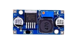
The LM2596 is a step-down (buck) voltage regulator designed to efficiently convert a higher input voltage into a stable, lower output voltage. It is capable of delivering up to 3A of output current, making it ideal for powering a wide range of electronic devices. The LM2596 is known for its high efficiency, ease of use, and reliability, which makes it a popular choice for power supply applications.
Explore Projects Built with LM2596


Explore Projects Built with LM2596
Common Applications and Use Cases
- DC-DC power supply modules
- Battery-powered devices
- Voltage regulation for microcontrollers and sensors
- LED drivers
- Industrial and automotive electronics
Technical Specifications
The LM2596 is available in various fixed output voltage versions (e.g., 3.3V, 5V, 12V) as well as an adjustable version. Below are the key technical details:
Key Specifications
| Parameter | Value |
|---|---|
| Input Voltage Range | 4.5V to 40V |
| Output Voltage Range | 1.23V to 37V (adjustable version) |
| Maximum Output Current | 3A |
| Efficiency | Up to 90% |
| Switching Frequency | 150 kHz |
| Output Voltage Tolerance | ±4% |
| Operating Temperature | -40°C to +125°C |
Pin Configuration and Descriptions
The LM2596 is typically available in a 5-pin TO-220 package. Below is the pinout and description:
| Pin Number | Pin Name | Description |
|---|---|---|
| 1 | VIN | Input voltage pin. Connect to the unregulated DC input voltage. |
| 2 | Output | Regulated output voltage pin. Connect to the load. |
| 3 | Ground (GND) | Ground pin. Connect to the negative terminal of the input and output. |
| 4 | Feedback | Feedback pin. Used to set the output voltage (for adjustable versions). |
| 5 | ON/OFF | Enable pin. Connect to ground to enable the regulator, or to VIN to disable. |
Usage Instructions
How to Use the LM2596 in a Circuit
- Determine Input and Output Voltages: Ensure the input voltage is within the range of 4.5V to 40V and that the desired output voltage is within the regulator's capabilities.
- Select the Correct Version: Use a fixed voltage version (e.g., 5V) for standard applications or the adjustable version for custom output voltages.
- Connect the Pins:
- Connect the input voltage to the
VINpin. - Connect the load to the
Outputpin. - Connect the
GNDpin to the ground of the circuit. - For adjustable versions, use a resistor divider network on the
Feedbackpin to set the desired output voltage.
- Connect the input voltage to the
- Add External Components:
- Place an input capacitor (e.g., 100 µF) between
VINandGNDto stabilize the input voltage. - Place an output capacitor (e.g., 220 µF) between
OutputandGNDto reduce output voltage ripple. - Use an inductor (e.g., 33 µH) and a Schottky diode (e.g., 1N5822) as part of the buck converter circuit.
- Place an input capacitor (e.g., 100 µF) between
Important Considerations and Best Practices
- Heat Dissipation: The LM2596 can generate heat during operation, especially at high currents. Use a heatsink or ensure proper ventilation to prevent overheating.
- Input Voltage Margin: Ensure the input voltage is at least 3V higher than the desired output voltage for proper regulation.
- Output Voltage Adjustment: For adjustable versions, calculate the resistor values for the feedback network using the formula: [ V_{OUT} = V_{REF} \times \left(1 + \frac{R_2}{R_1}\right) ] where ( V_{REF} = 1.23V ).
Example: Using LM2596 with Arduino UNO
The LM2596 can be used to power an Arduino UNO from a higher voltage source (e.g., a 12V battery). Below is an example circuit and code:
Circuit Connections
- Connect the 12V input to the
VINpin of the LM2596. - Set the output voltage to 5V (for adjustable versions) using a resistor divider.
- Connect the
Outputpin of the LM2596 to the 5V pin of the Arduino UNO. - Connect the
GNDpin of the LM2596 to the Arduino's GND.
Arduino Code Example
// Example code to blink an LED using Arduino UNO powered by LM2596
// Ensure the LM2596 output is set to 5V before connecting to the Arduino

const int ledPin = 13; // Pin connected to the onboard LED

void setup() {
  pinMode(ledPin, OUTPUT); // Set the LED pin as an output
}

void loop() {
  digitalWrite(ledPin, HIGH); // Turn the LED on
  delay(1000);                // Wait for 1 second
  digitalWrite(ledPin, LOW);  // Turn the LED off
  delay(1000);                // Wait for 1 second
}
Troubleshooting and FAQs
Common Issues and Solutions
No Output Voltage:
- Check the input voltage. Ensure it is within the specified range (4.5V to 40V).
- Verify all connections, especially the
GNDandVINpins. - Ensure the
ON/OFFpin is connected to ground to enable the regulator.
Output Voltage is Incorrect:
- For adjustable versions, verify the resistor values in the feedback network.
- Check for loose or incorrect connections.
Excessive Heat:
- Ensure the input voltage is not excessively high compared to the output voltage.
- Use a heatsink or improve ventilation.
High Output Ripple:
- Increase the value of the output capacitor.
- Ensure the inductor and Schottky diode are correctly rated.
FAQs
Q: Can the LM2596 be used with a 24V input to power a 5V device?
A: Yes, the LM2596 can step down a 24V input to 5V, provided the input voltage is stable and the output current does not exceed 3A.
Q: What is the efficiency of the LM2596?
A: The LM2596 can achieve up to 90% efficiency, depending on the input voltage, output voltage, and load conditions.
Q: Can I use the LM2596 without a heatsink?
A: For low current applications (e.g., <1A), a heatsink may not be necessary. However, for higher currents, a heatsink is recommended to prevent overheating.
Q: Is the LM2596 suitable for battery-powered applications?
A: Yes, the LM2596 is highly efficient and suitable for battery-powered devices, as it minimizes power loss.