How to Use RGB Colour Sensor: Examples, Pinouts, and Specs
Introduction
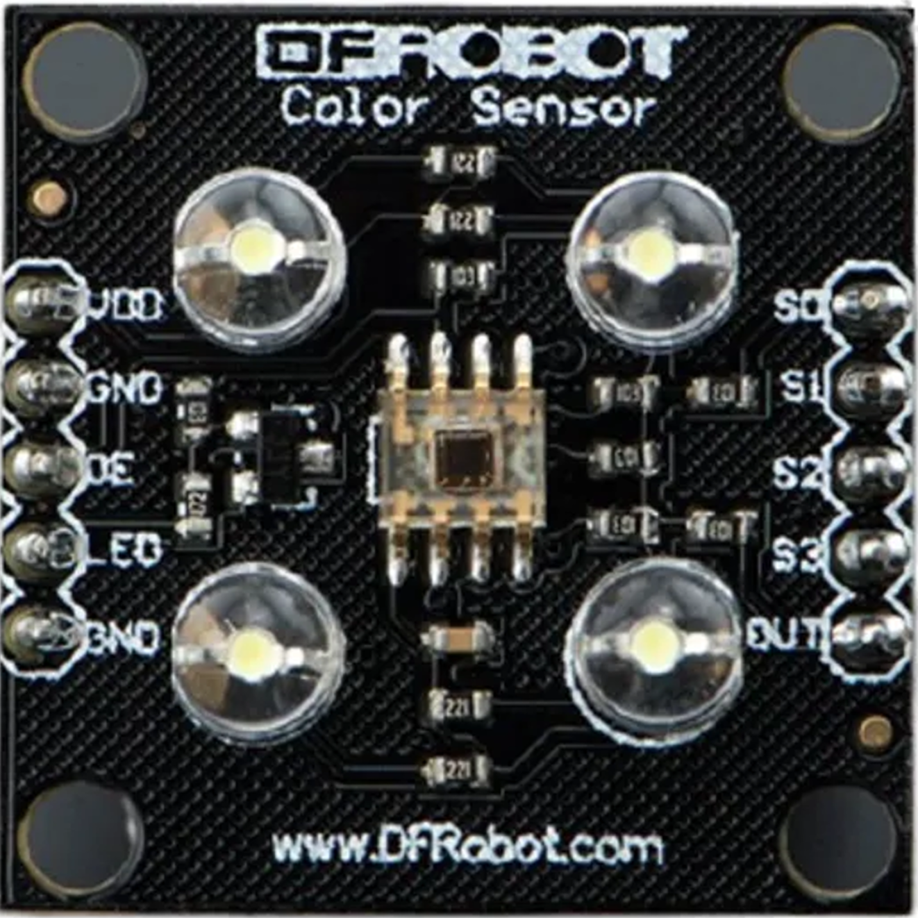
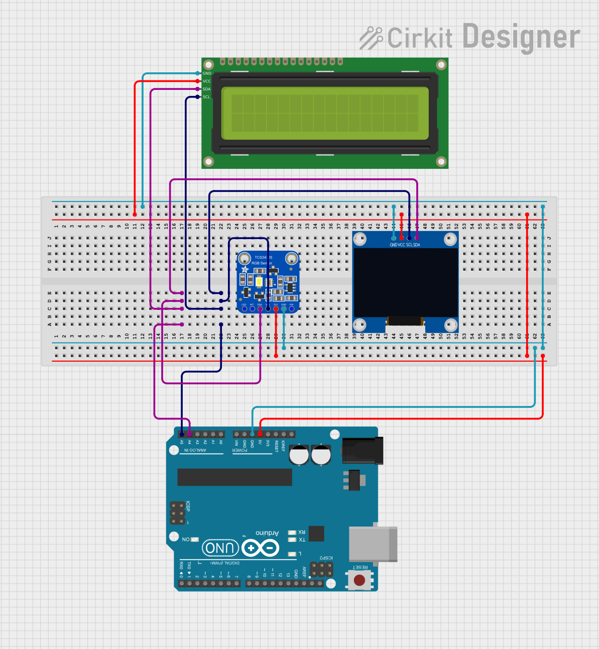
The TCS3200 is an RGB Colour Sensor designed and manufactured by DFRobot. It is capable of detecting and measuring the intensity of red, green, and blue light components, allowing it to determine the color of an object or light source. This sensor is widely used in applications such as color sorting, ambient light sensing, and color matching in various industries, including automation, electronics, and robotics.
Explore Projects Built with RGB Colour Sensor
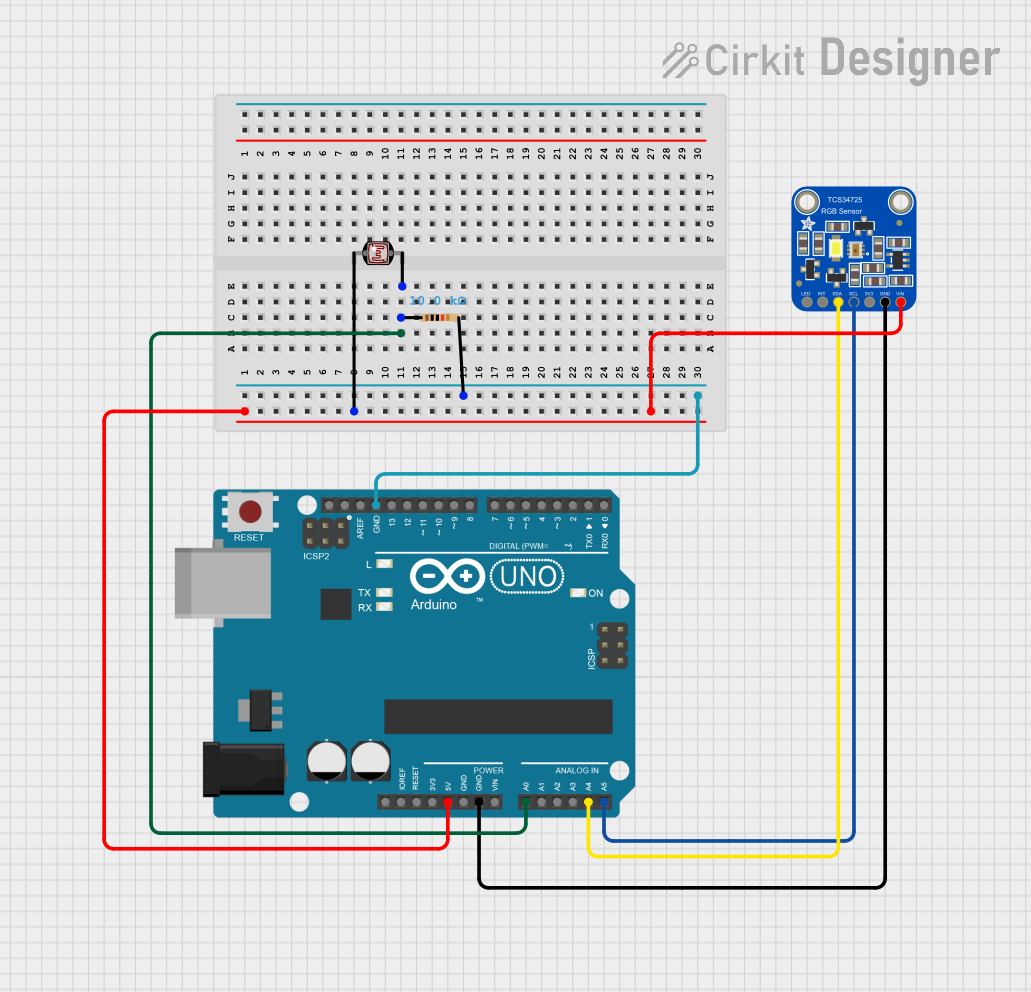
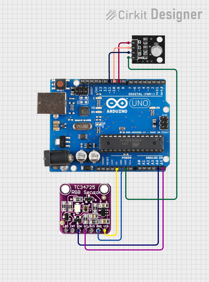
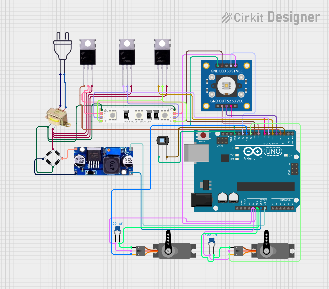
Explore Projects Built with RGB Colour Sensor
Technical Specifications
Key Technical Details
- Supply Voltage (Vdd): 2.7V - 5.5V
- High-Resolution Conversion: 8MHz
- Output Frequency: Scalable from 2% to 100%
- Response Time: 28ms (typical)
- Peak Sensitivity Wavelengths:
- Red: 615nm
- Green: 530nm
- Blue: 465nm
Pin Configuration and Descriptions
| Pin Number | Pin Name | Description |
|---|---|---|
| 1 | Vdd | Power supply (2.7V - 5.5V) |
| 2 | GND | Ground |
| 3 | OE | Output enable (active low) |
| 4 | OUT | Output frequency (square wave) |
| 5 | S0 | Output frequency scaling selection input 0 |
| 6 | S1 | Output frequency scaling selection input 1 |
| 7 | S2 | Photodiode type selection input 0 |
| 8 | S3 | Photodiode type selection input 1 |
Usage Instructions
Connecting to a Circuit
- Connect the Vdd pin to a 2.7V - 5.5V power supply.
- Connect the GND pin to the ground of the power supply.
- Connect the OE pin to ground to enable the output (or to a microcontroller pin for controlled enabling).
- Connect the OUT pin to a microcontroller's input capture pin to read the frequency.
- Set S0 and S1 to configure the output frequency scaling (refer to the datasheet for specific configurations).
- Set S2 and S3 to select the type of photodiode (red, green, blue, or clear).
Best Practices
- Ensure that the power supply is stable and within the specified voltage range.
- Avoid exposing the sensor to direct sunlight or strong artificial light sources that could saturate the sensor.
- Use appropriate filtering capacitors close to the Vdd and GND pins to minimize noise.
- When connecting to a microcontroller, use short and direct wiring to reduce signal degradation.
Example Code for Arduino UNO
// Define the TCS3200 pins connected to the Arduino
#define S0 4
#define S1 5
#define S2 6
#define S3 7
#define OUT 8

// Function to setup the TCS3200 sensor
void setupTCS3200() {
  pinMode(S0, OUTPUT);
  pinMode(S1, OUTPUT);
  pinMode(S2, OUTPUT);
  pinMode(S3, OUTPUT);
  pinMode(OUT, INPUT);

  // Set frequency scaling to 20%
  digitalWrite(S0, HIGH);
  digitalWrite(S1, LOW);
}

// Function to read the frequency from the TCS3200 sensor
unsigned int readColorFrequency() {
  // Set the photodiode type to red
  digitalWrite(S2, LOW);
  digitalWrite(S3, LOW);
  // Read the output frequency
  unsigned int frequency = pulseIn(OUT, LOW);
  return frequency;
}

void setup() {
  Serial.begin(9600);
  setupTCS3200();
}

void loop() {
  unsigned int redFrequency = readColorFrequency();
  Serial.print("Red Frequency: ");
  Serial.println(redFrequency);
  delay(1000);
}
Troubleshooting and FAQs
Common Issues
- No Output Signal: Ensure that the OE pin is connected properly and that the sensor is powered.
- Inaccurate Color Readings: Check if the sensor is calibrated correctly and not exposed to external light interference.
- Erratic Readings: Verify that the power supply is stable and that there are no loose connections.
Solutions and Tips
- Calibration: Perform calibration in the same lighting conditions as the intended application.
- Shielding: Use a light shield to prevent external light from affecting the sensor readings.
- Filtering: Add a low-pass filter to the OUT pin if there is significant electrical noise.
FAQs
Q: Can the TCS3200 sensor detect non-visible light? A: No, the TCS3200 is designed to detect visible light in the red, green, and blue spectrum.
Q: How do I calibrate the sensor for accurate color detection? A: Calibration involves recording the sensor's output for known colors under controlled lighting conditions and using these values as references in your application.
Q: What is the maximum sensing distance for the TCS3200 sensor? A: The effective sensing distance depends on the light intensity and the object's surface but is typically a few centimeters.
Q: Can I use the TCS3200 sensor with a 3.3V microcontroller? A: Yes, the TCS3200 can operate at voltages as low as 2.7V, making it compatible with 3.3V systems.