How to Use GROVE LCD SCREEN SEED STUDIO: Examples, Pinouts, and Specs
Introduction
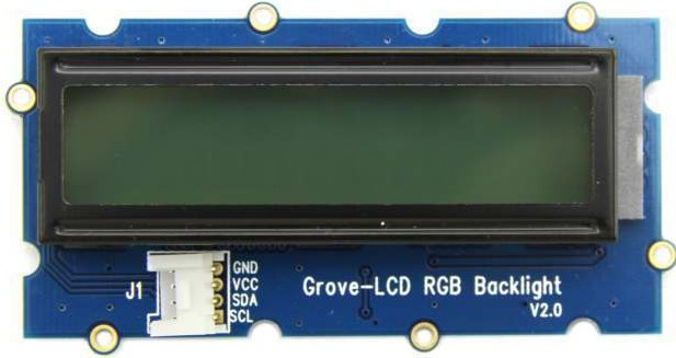
The GROVE LCD Screen by Seeed Studio is a versatile LCD display module designed for seamless integration with Grove-compatible systems. It features a user-friendly interface for displaying text and basic graphics, making it an excellent choice for projects requiring visual output. This module is particularly popular for its simplicity, compact design, and compatibility with microcontrollers like Arduino.
Explore Projects Built with GROVE LCD SCREEN SEED STUDIO


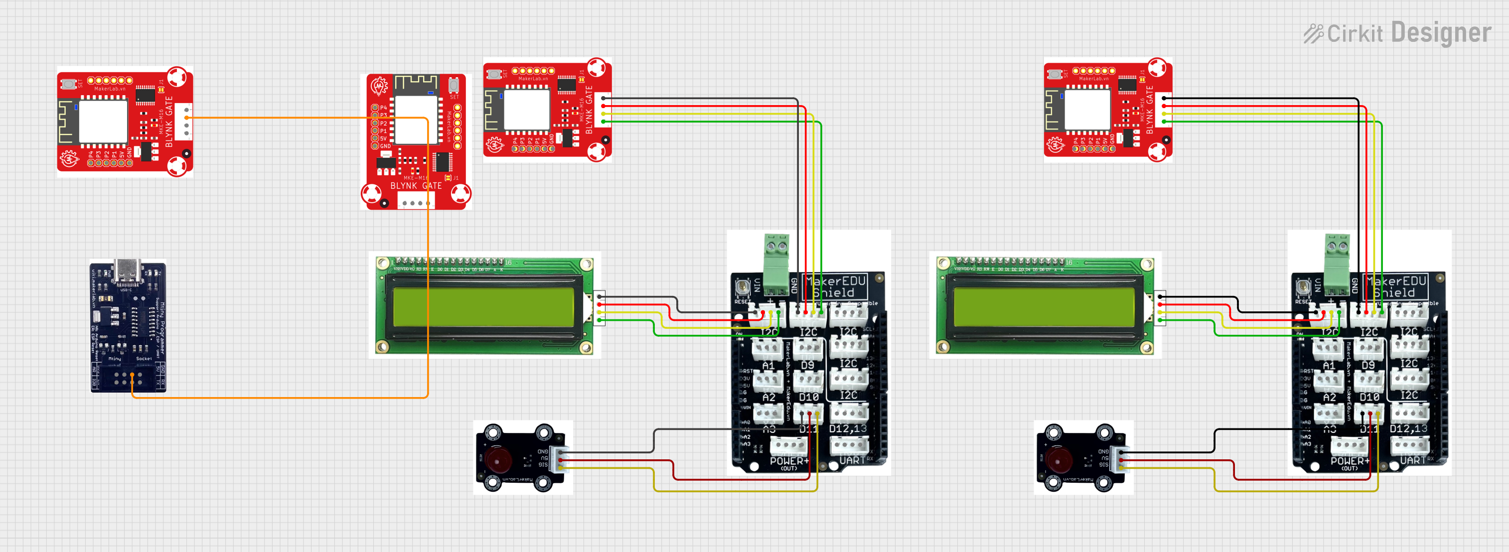

Explore Projects Built with GROVE LCD SCREEN SEED STUDIO
Common Applications and Use Cases
- Displaying sensor data in real-time
- Creating user interfaces for embedded systems
- Educational projects and prototyping
- IoT devices requiring visual feedback
- Menu systems for small electronic devices
Technical Specifications
Below are the key technical details of the GROVE LCD Screen:
| Specification | Details |
|---|---|
| Operating Voltage | 5V |
| Communication Interface | I2C |
| I2C Address (Default) | 0x3E |
| Display Type | 16x2 character LCD |
| Backlight Color | RGB (customizable) |
| Dimensions | 80mm x 36mm x 18mm |
| Operating Temperature | -20°C to 70°C |
| Power Consumption | < 100mW |
Pin Configuration and Descriptions
The GROVE LCD Screen uses a 4-pin Grove connector for communication and power. Below is the pin configuration:
| Pin | Name | Description |
|---|---|---|
| 1 | GND | Ground (0V reference) |
| 2 | VCC | Power supply (5V) |
| 3 | SDA | I2C data line |
| 4 | SCL | I2C clock line |
Usage Instructions
How to Use the GROVE LCD Screen in a Circuit
- Connect the Module: Use a Grove cable to connect the LCD screen to an I2C port on a Grove Base Shield or directly to the I2C pins of your microcontroller.
- Power the Module: Ensure the microcontroller is powered with 5V, as the LCD operates at this voltage.
- Install Required Libraries: If using Arduino, install the
Grove_LCD_RGB_Backlightlibrary from the Arduino Library Manager. - Write and Upload Code: Use the example code below to display text and control the backlight color.
Important Considerations and Best Practices
- I2C Address: Ensure no other devices on the I2C bus share the same address (default: 0x3E).
- Power Supply: Use a stable 5V power source to avoid flickering or malfunction.
- Backlight Control: Avoid rapid changes to the RGB backlight to prevent wear on the LEDs.
- Cable Length: Keep the Grove cable short to minimize signal degradation on the I2C lines.
Example Code for Arduino UNO
Below is an example code snippet to display "Hello, World!" on the LCD and set the backlight to blue:
#include <Wire.h>
#include "rgb_lcd.h"

// Create an instance of the LCD object
rgb_lcd lcd;

// Define RGB backlight color
const int colorR = 0;  // Red component (0-255)
const int colorG = 0;  // Green component (0-255)
const int colorB = 255; // Blue component (0-255)

void setup() {
  // Initialize the LCD
  lcd.begin(16, 2); // 16 columns, 2 rows

  // Set the backlight color
  lcd.setRGB(colorR, colorG, colorB);

  // Display a message on the LCD
  lcd.print("Hello, World!");
}

void loop() {
  // No actions in the loop for this example
}
Notes on the Code
- The
rgb_lcdlibrary simplifies communication with the GROVE LCD Screen. - The
lcd.setRGB()function allows you to customize the backlight color by specifying RGB values.
Troubleshooting and FAQs
Common Issues and Solutions
No Display Output:
- Ensure the module is properly connected to the I2C port.
- Verify the power supply is 5V and stable.
- Check the I2C address in the code matches the module's default (0x3E).
Flickering or Dim Backlight:
- Confirm the power source can supply sufficient current.
- Avoid using excessively long Grove cables.
Text Not Displaying Correctly:
- Ensure the
Grove_LCD_RGB_Backlightlibrary is installed and up to date. - Verify the
lcd.begin(16, 2)function matches the display's dimensions.
- Ensure the
I2C Communication Errors:
- Check for address conflicts with other I2C devices.
- Use pull-up resistors on the SDA and SCL lines if necessary.
FAQs
Q: Can I use this module with a Raspberry Pi?
A: Yes, the GROVE LCD Screen is compatible with Raspberry Pi. Use the I2C pins and appropriate Python libraries like smbus.
Q: How do I change the backlight color?
A: Use the lcd.setRGB(r, g, b) function in your code, where r, g, and b are the red, green, and blue intensity values (0-255).
Q: What is the maximum cable length for I2C communication?
A: For reliable communication, keep the cable length under 50cm. Longer cables may require additional pull-up resistors.
Q: Can I display custom characters?
A: Yes, the module supports custom characters. Refer to the library documentation for details on creating and displaying them.
This documentation provides a comprehensive guide to using the GROVE LCD Screen by Seeed Studio. With its ease of use and versatility, this module is an excellent addition to any electronics project!