How to Use LCD Display (16 pin): Examples, Pinouts, and Specs
Introduction
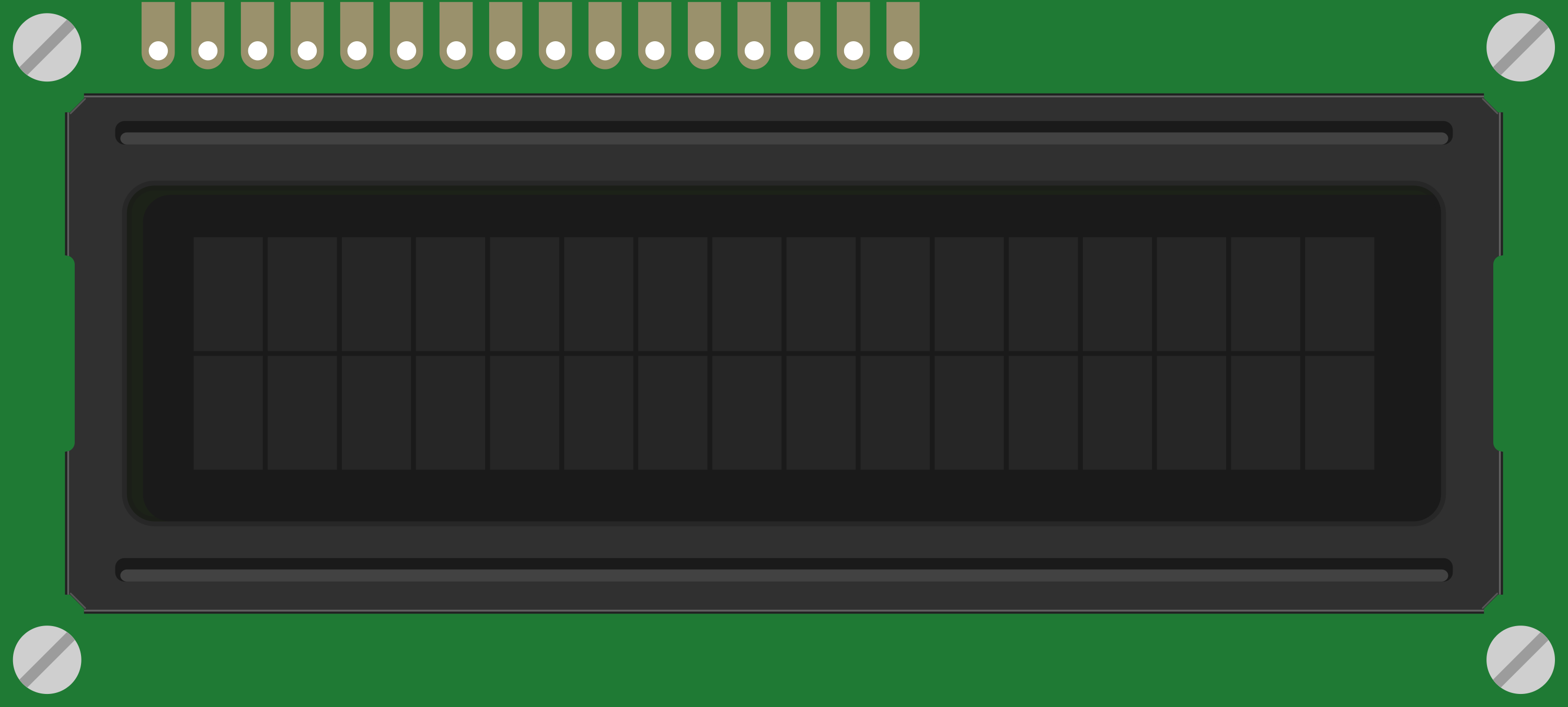
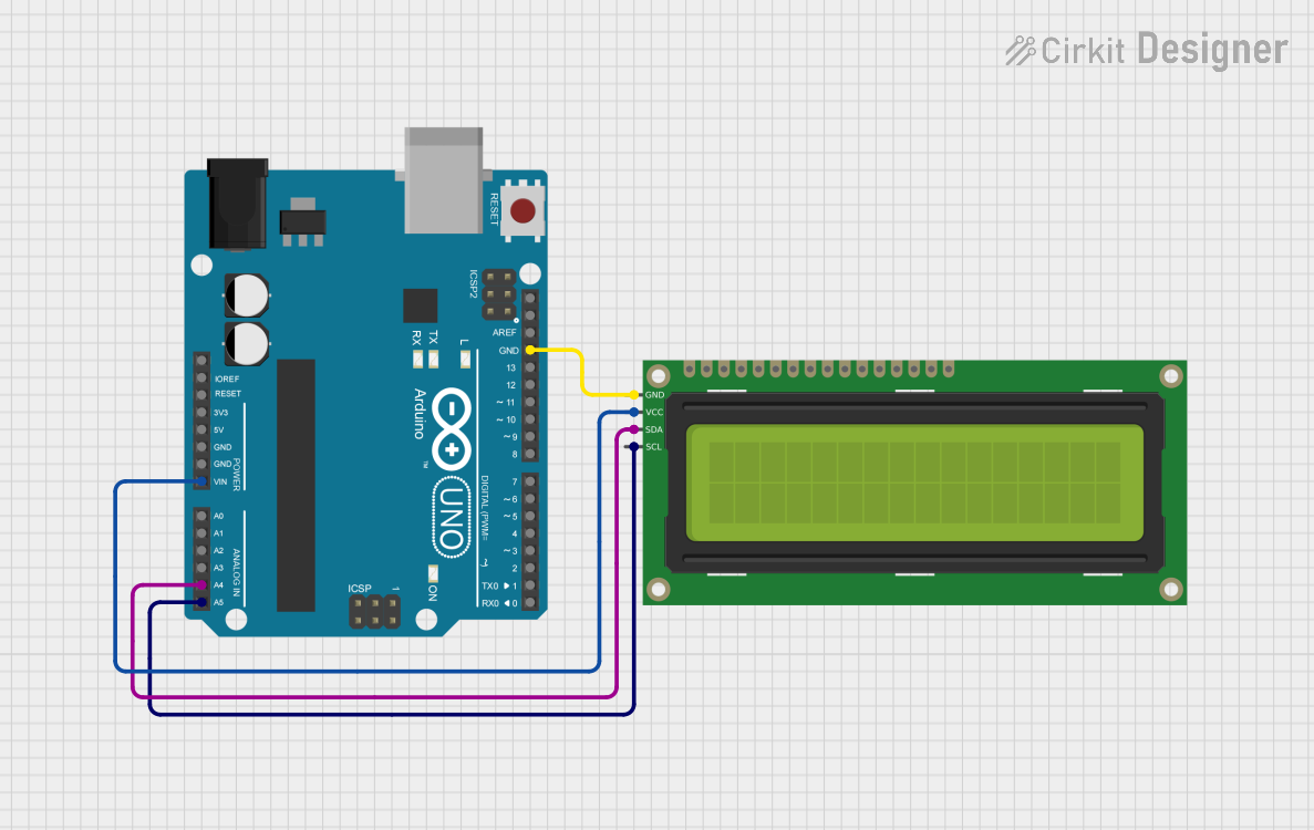
A 16-pin LCD display is a flat-panel display that uses liquid crystals to produce images. It is widely used in embedded systems for displaying text, numbers, and simple graphics. This component is ideal for applications where a compact and low-power display is required. Common use cases include digital clocks, temperature monitors, and user interfaces for microcontroller-based projects.
Explore Projects Built with LCD Display (16 pin)

Explore Projects Built with LCD Display (16 pin)
Technical Specifications
- Display Type: Alphanumeric LCD
- Characters: Typically 16x2 (16 characters per row, 2 rows)
- Operating Voltage: 4.7V to 5.3V
- Current Consumption: ~1mA (without backlight), ~15mA (with backlight)
- Interface: Parallel (4-bit or 8-bit mode)
- Backlight: LED (optional, controlled via pin 15 and 16)
- Operating Temperature: -20°C to 70°C
- Dimensions: Varies by model, typically 80mm x 36mm x 12mm
Pin Configuration and Descriptions
The 16-pin LCD display has the following pinout:
| Pin No. | Name | Description |
|---|---|---|
| 1 | VSS | Ground (0V) |
| 2 | VDD | Power supply (4.7V to 5.3V) |
| 3 | V0 | Contrast adjustment (connect to a potentiometer for contrast control) |
| 4 | RS | Register Select (0: Command mode, 1: Data mode) |
| 5 | RW | Read/Write (0: Write to LCD, 1: Read from LCD) |
| 6 | E | Enable signal (triggers data read/write) |
| 7 | D0 | Data bit 0 (used in 8-bit mode only) |
| 8 | D1 | Data bit 1 (used in 8-bit mode only) |
| 9 | D2 | Data bit 2 (used in 8-bit mode only) |
| 10 | D3 | Data bit 3 (used in 8-bit mode only) |
| 11 | D4 | Data bit 4 (used in both 4-bit and 8-bit modes) |
| 12 | D5 | Data bit 5 (used in both 4-bit and 8-bit modes) |
| 13 | D6 | Data bit 6 (used in both 4-bit and 8-bit modes) |
| 14 | D7 | Data bit 7 (used in both 4-bit and 8-bit modes) |
| 15 | LED+ | Backlight anode (connect to +5V via a resistor for backlight control) |
| 16 | LED- | Backlight cathode (connect to ground) |
Usage Instructions
How to Use the Component in a Circuit
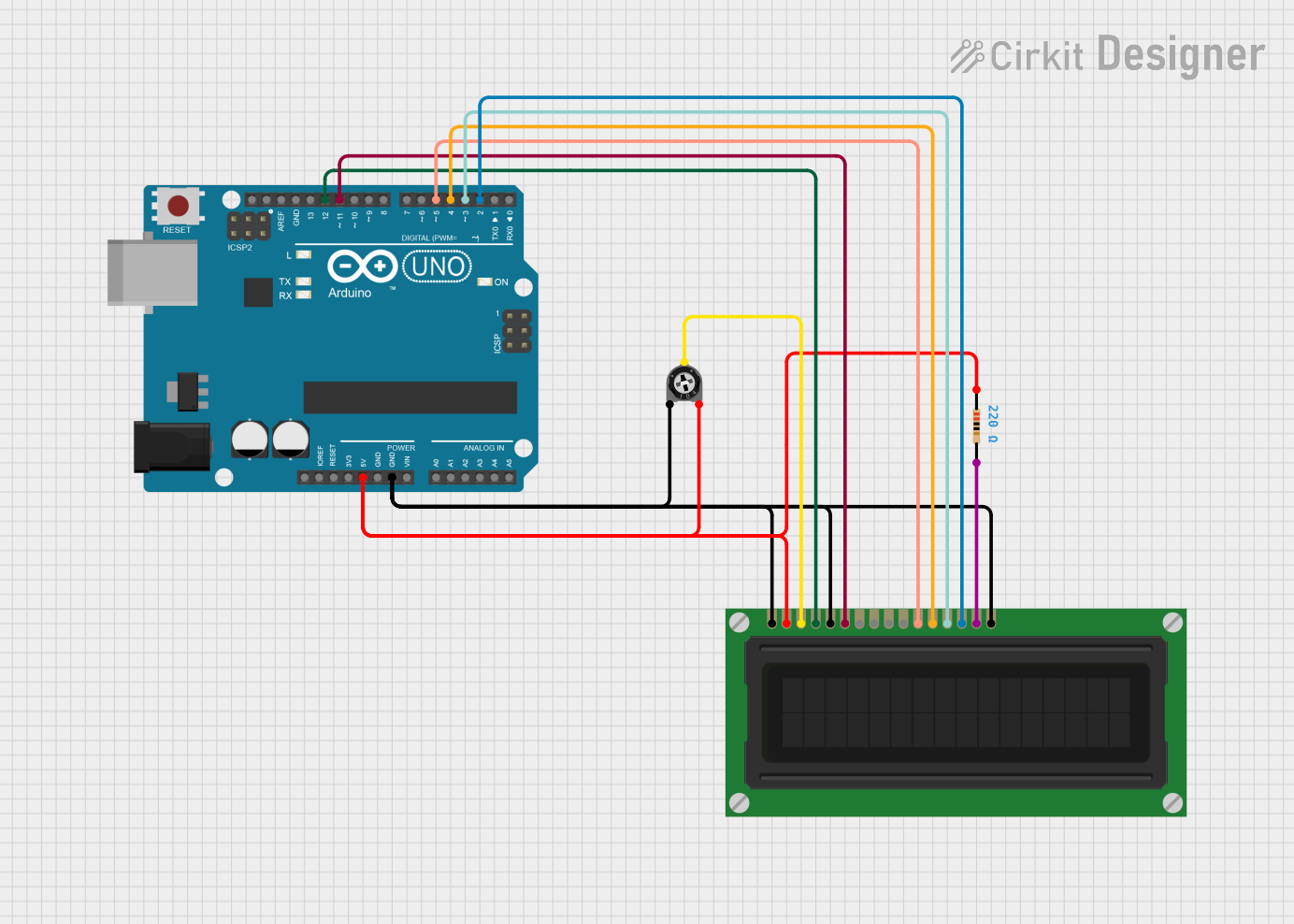
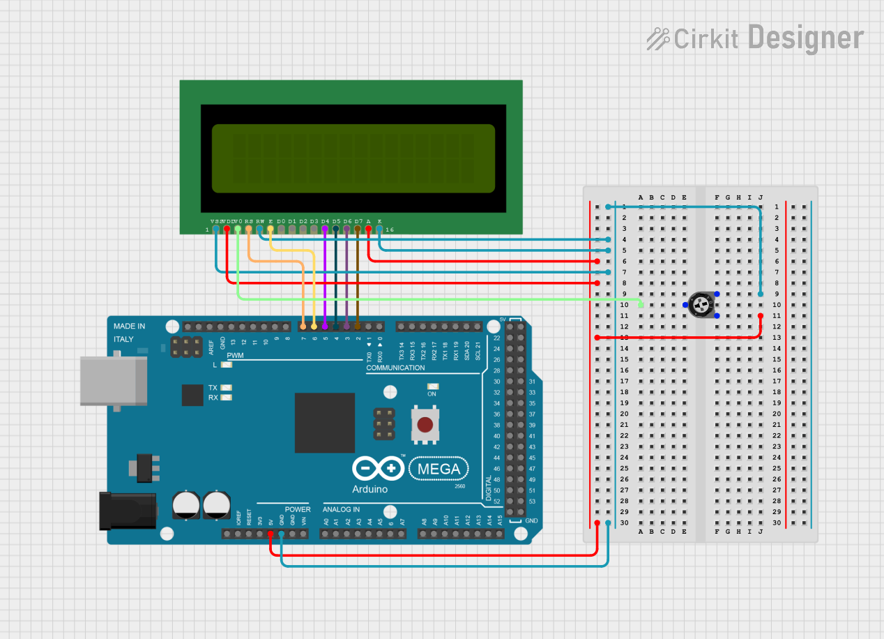
- Power the LCD: Connect pin 1 (VSS) to ground and pin 2 (VDD) to a 5V power supply.
- Adjust Contrast: Connect pin 3 (V0) to the wiper of a 10kΩ potentiometer. Connect one end of the potentiometer to ground and the other to 5V. Adjust the potentiometer to set the display contrast.
- Control Pins: Connect pins 4 (RS), 5 (RW), and 6 (E) to digital output pins of a microcontroller.
- Data Pins: For 4-bit mode, connect pins 11-14 (D4-D7) to the microcontroller. For 8-bit mode, connect pins 7-14 (D0-D7).
- Backlight: Connect pin 15 (LED+) to 5V through a 220Ω resistor and pin 16 (LED-) to ground.
Arduino UNO Example Code
Below is an example of how to use a 16-pin LCD display in 4-bit mode with an Arduino UNO:
#include <LiquidCrystal.h>

// Initialize the library with the numbers of the interface pins
// RS -> pin 7, E -> pin 8, D4 -> pin 9, D5 -> pin 10, D6 -> pin 11, D7 -> pin 12
LiquidCrystal lcd(7, 8, 9, 10, 11, 12);

void setup() {
  // Set up the LCD's number of columns and rows
  lcd.begin(16, 2);

  // Print a message to the LCD
  lcd.print("Hello, World!");
}

void loop() {
  // Set the cursor to column 0, line 1 (second row)
  lcd.setCursor(0, 1);

  // Print the current time in seconds since the Arduino started
  lcd.print(millis() / 1000);
}
Important Considerations and Best Practices
- Always use a current-limiting resistor (e.g., 220Ω) for the backlight to prevent damage.
- Use a 10kΩ potentiometer for contrast adjustment to ensure optimal visibility.
- Avoid leaving the RW pin floating; connect it to ground if you only intend to write to the LCD.
- For longer cables between the microcontroller and the LCD, consider using pull-up resistors on the data lines to reduce noise.
Troubleshooting and FAQs
Common Issues and Solutions
No Display on the Screen:
- Ensure the power supply is connected to pins 1 (VSS) and 2 (VDD).
- Check the contrast adjustment (pin 3, V0). Adjust the potentiometer until the text is visible.
- Verify the backlight connections (pins 15 and 16).
Random Characters or No Response:
- Ensure the data pins (D4-D7 or D0-D7) are correctly connected to the microcontroller.
- Check the RS, RW, and E pin connections.
- Verify that the LCD is initialized correctly in the code.
Backlight Not Working:
- Check the resistor value connected to pin 15 (LED+). Use a 220Ω resistor.
- Ensure pin 16 (LED-) is connected to ground.
Text Appears Garbled:
- Ensure the LCD is in the correct mode (4-bit or 8-bit) as configured in the code.
- Double-check the wiring for loose or incorrect connections.
FAQs
Q: Can I use the LCD without a backlight?
A: Yes, the LCD can function without a backlight, but visibility may be reduced in low-light conditions.
Q: What is the maximum cable length between the LCD and the microcontroller?
A: For reliable operation, keep the cable length under 30cm. Use pull-up resistors for longer distances.
Q: Can I power the LCD with 3.3V?
A: Most 16-pin LCDs require 5V for proper operation. Check your specific model's datasheet for compatibility with 3.3V.
Q: How do I display custom characters?
A: Use the createChar() function in the LiquidCrystal library to define and display custom characters.
By following this documentation, you can effectively integrate and troubleshoot a 16-pin LCD display in your projects.