How to Use pic16f887: Examples, Pinouts, and Specs
Introduction
The PIC16F887 is an 8-bit microcontroller manufactured by Microchip Technology. It is a versatile and powerful device, featuring 40 pins, 368 bytes of RAM, 256 bytes of EEPROM, and a 14-bit instruction set. This microcontroller is equipped with a variety of peripherals, including timers, analog-to-digital converters (ADC), pulse-width modulation (PWM), and communication interfaces, making it ideal for a wide range of embedded applications.
Explore Projects Built with pic16f887
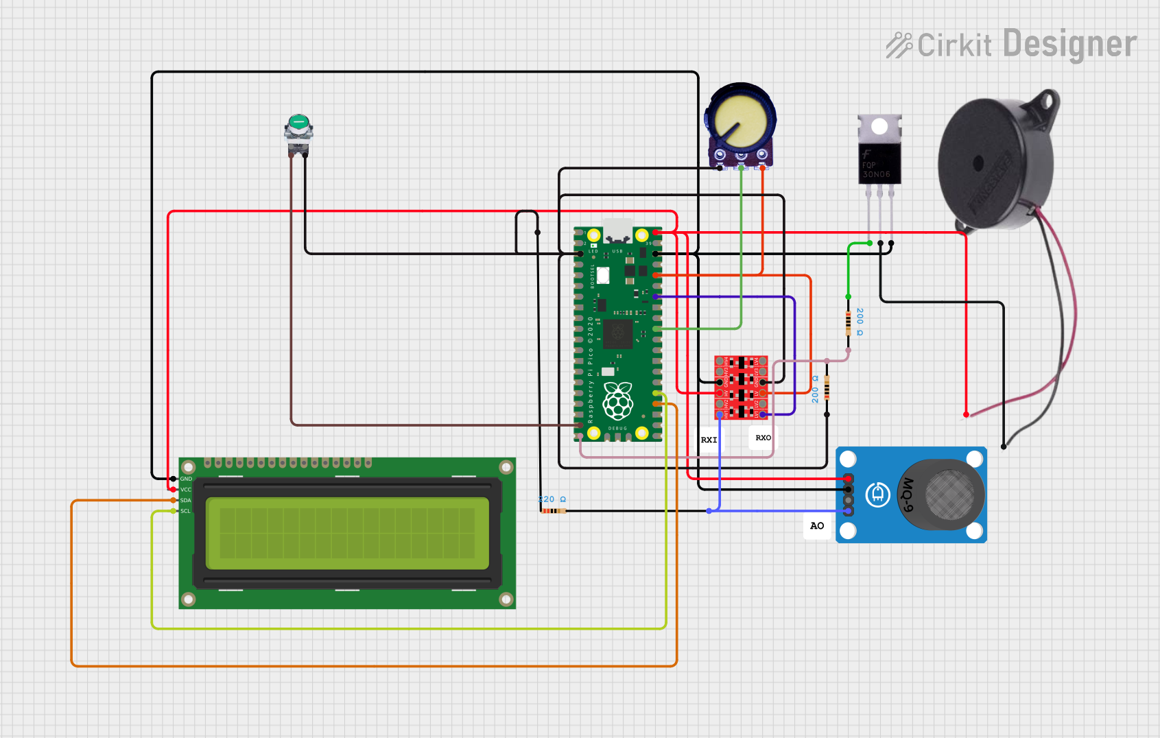
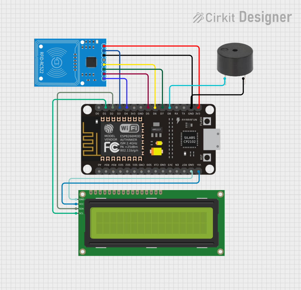


Explore Projects Built with pic16f887
Common Applications
- Home automation systems
- Industrial control systems
- Robotics and motor control
- Sensor interfacing and data acquisition
- Educational and prototyping projects
Technical Specifications
Key Technical Details
| Parameter | Value |
|---|---|
| Architecture | 8-bit |
| Program Memory | 8 KB (Flash) |
| Data Memory | 368 bytes (RAM) |
| EEPROM | 256 bytes |
| Instruction Set | 14-bit |
| Operating Voltage | 2.0V to 5.5V |
| Clock Speed | Up to 20 MHz |
| I/O Pins | 36 |
| ADC Resolution | 10-bit |
| Timers | 3 (Timer0, Timer1, Timer2) |
| Communication Interfaces | USART, I2C, SPI |
| PWM Channels | 2 |
| Package Types | DIP-40, QFN-44, TQFP-44 |
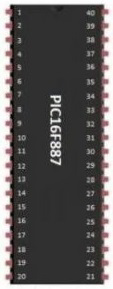
Pin Configuration and Descriptions
The PIC16F887 has 40 pins, with the following key pin functions:
| Pin Number | Pin Name | Description |
|---|---|---|
| 1 | MCLR/VPP | Master Clear (Reset) input or programming voltage |
| 2-7 | RA0-RA5 | Analog/Digital I/O pins |
| 8 | VSS | Ground |
| 9-10 | OSC1/OSC2 | Oscillator input/output |
| 11-18 | RB0-RB7 | Digital I/O pins |
| 19 | VDD | Positive supply voltage |
| 20-27 | RC0-RC7 | Digital I/O pins |
| 28-33 | RD0-RD5 | Digital I/O pins |
| 34-37 | RE0-RE3 | Analog/Digital I/O pins |
| 38 | VSS | Ground |
| 39 | VDD | Positive supply voltage |
| 40 | RA6/OSC2 | Digital I/O or Oscillator output |
Usage Instructions
How to Use the PIC16F887 in a Circuit
- Power Supply: Connect the VDD pin to a 5V power source and the VSS pin to ground.
- Oscillator Configuration: Connect an external crystal oscillator (e.g., 4 MHz) between OSC1 and OSC2 pins, along with appropriate capacitors.
- Reset Pin: Connect the MCLR pin to 5V through a 10kΩ pull-up resistor. For in-circuit programming, ensure this pin is accessible.
- I/O Pins: Configure the I/O pins (RA, RB, RC, RD, RE) as input or output in the software, depending on your application.
- Programming: Use an ICSP (In-Circuit Serial Programming) tool to load your program into the microcontroller.
Important Considerations and Best Practices
- Decoupling Capacitors: Place a 0.1µF capacitor close to the VDD and VSS pins to reduce noise.
- Unused Pins: Configure unused pins as outputs or connect them to ground through a resistor to avoid floating states.
- Clock Source: Choose an appropriate clock source (internal or external) based on your application's timing requirements.
- Programming Voltage: Ensure the MCLR pin receives the correct programming voltage (VPP) during programming.
Example Code for Arduino UNO Integration
The PIC16F887 can communicate with an Arduino UNO via UART. Below is an example of Arduino code to send data to the PIC16F887:
// Arduino UNO UART Communication with PIC16F887
// Sends a message to the PIC16F887 via Serial

void setup() {
  Serial.begin(9600); // Initialize UART at 9600 baud rate
}

void loop() {
  Serial.println("Hello, PIC16F887!"); // Send data to PIC16F887
  delay(1000); // Wait for 1 second
}
On the PIC16F887 side, configure the USART module to receive the data.
Troubleshooting and FAQs
Common Issues and Solutions
Microcontroller Not Responding
- Cause: Incorrect power supply or missing decoupling capacitors.
- Solution: Verify the VDD and VSS connections and add a 0.1µF capacitor near the power pins.
Program Not Running
- Cause: Incorrect oscillator configuration.
- Solution: Check the crystal oscillator connections and ensure the correct fuse settings are used during programming.
Communication Failure with Arduino
- Cause: Mismatched baud rates or incorrect wiring.
- Solution: Ensure both devices use the same baud rate and verify the TX and RX connections.
Floating Pins
- Cause: Unused pins left unconnected.
- Solution: Configure unused pins as outputs or connect them to ground through resistors.
FAQs
Q: Can the PIC16F887 operate without an external oscillator?
A: Yes, the PIC16F887 has an internal oscillator that can be used for low-speed applications.
Q: How do I store data permanently on the PIC16F887?
A: Use the built-in 256 bytes of EEPROM to store data that needs to persist after power loss.
Q: What is the maximum clock speed of the PIC16F887?
A: The PIC16F887 can operate at a maximum clock speed of 20 MHz with an external oscillator.
Q: Can I use the PIC16F887 for PWM applications?
A: Yes, the PIC16F887 has two PWM channels that can be used for motor control, LED dimming, and other applications.