Cirkit Designer Logo
Cirkit Designer
Your all-in-one circuit design IDE
Home / 
Component Documentation

How to Use Microwave Radar 24GHz: Examples, Pinouts, and Specs

Image of Microwave Radar 24GHz
Cirkit Designer LogoDesign with Microwave Radar 24GHz in Cirkit Designer

Introduction

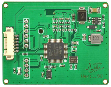
The DFRobot SEN0306 is a 24GHz microwave radar module designed for object detection, distance measurement, and speed sensing. Operating at a high frequency of 24GHz, this radar system is ideal for applications requiring precise and reliable detection, such as automotive collision avoidance, speed monitoring, and industrial automation. Its compact design and robust performance make it suitable for both indoor and outdoor environments.

Explore Projects Built with Microwave Radar 24GHz

Use Cirkit Designer to design, explore, and prototype these projects online. Some projects support real-time simulation. Click "Open Project" to start designing instantly!
Arduino UNO and Seeed mmWave 24GHz Sensor for Proximity Detection
Image of Seeed to Arduino UNO: A project utilizing Microwave Radar 24GHz in a practical application
This circuit consists of an Arduino UNO microcontroller connected to a Seeed mmWave 24GHz sensor. The Arduino UNO provides power to the sensor and communicates with it via analog pins A2 and A3, which are connected to the sensor's Tx and Rx pins, respectively.
Cirkit Designer LogoOpen Project in Cirkit Designer
Arduino Mega 2560 and ESP32 CAM Based Motion Detection and RFID Security System
Image of Arduino Mega Circuit: A project utilizing Microwave Radar 24GHz in a practical application
This circuit is designed for a multi-sensor motion detection system with image capture and RFID reading capabilities. It uses an Arduino Mega 2560 as the central processing unit, interfacing with microwave radar motion sensors, an ESP32 CAM, and RFID boards. Power management is handled by voltage regulators and DC-DC converters, and an Arduino MKR WiFi 1010 is included for potential wireless communication.
Cirkit Designer LogoOpen Project in Cirkit Designer
Arduino-Based Doppler Radar with RF Transmission and LCD Display
Image of Doppler Radar: A project utilizing Microwave Radar 24GHz in a practical application
This circuit features an Arduino UNO microcontroller interfaced with an RF 433 MHz Transmitter, a Transmitter RF Module, an LCD screen with I2C communication, and a doppler radar sensor. The Arduino controls the RF transmission and processes the doppler radar's signal, likely for motion detection purposes. The LCD screen is used to display information or statuses, and the RF modules enable wireless communication, possibly to transmit the processed radar data.
Cirkit Designer LogoOpen Project in Cirkit Designer
Raspberry Pi 4B and MMWave Radar Sensor-Based Smart LED Indicator
Image of Capstone Connections: A project utilizing Microwave Radar 24GHz in a practical application
This circuit integrates a Raspberry Pi 4B with an MMWave radar sensor and two LEDs (red and green). The Raspberry Pi powers and communicates with the radar sensor via GPIO pins, and controls the LEDs to indicate the status or results of the radar sensor's operation.
Cirkit Designer LogoOpen Project in Cirkit Designer

Explore Projects Built with Microwave Radar 24GHz

Use Cirkit Designer to design, explore, and prototype these projects online. Some projects support real-time simulation. Click "Open Project" to start designing instantly!
Image of Seeed to Arduino UNO: A project utilizing Microwave Radar 24GHz in a practical application
Arduino UNO and Seeed mmWave 24GHz Sensor for Proximity Detection
This circuit consists of an Arduino UNO microcontroller connected to a Seeed mmWave 24GHz sensor. The Arduino UNO provides power to the sensor and communicates with it via analog pins A2 and A3, which are connected to the sensor's Tx and Rx pins, respectively.
Cirkit Designer LogoOpen Project in Cirkit Designer
Image of Arduino Mega Circuit: A project utilizing Microwave Radar 24GHz in a practical application
Arduino Mega 2560 and ESP32 CAM Based Motion Detection and RFID Security System
This circuit is designed for a multi-sensor motion detection system with image capture and RFID reading capabilities. It uses an Arduino Mega 2560 as the central processing unit, interfacing with microwave radar motion sensors, an ESP32 CAM, and RFID boards. Power management is handled by voltage regulators and DC-DC converters, and an Arduino MKR WiFi 1010 is included for potential wireless communication.
Cirkit Designer LogoOpen Project in Cirkit Designer
Image of Doppler Radar: A project utilizing Microwave Radar 24GHz in a practical application
Arduino-Based Doppler Radar with RF Transmission and LCD Display
This circuit features an Arduino UNO microcontroller interfaced with an RF 433 MHz Transmitter, a Transmitter RF Module, an LCD screen with I2C communication, and a doppler radar sensor. The Arduino controls the RF transmission and processes the doppler radar's signal, likely for motion detection purposes. The LCD screen is used to display information or statuses, and the RF modules enable wireless communication, possibly to transmit the processed radar data.
Cirkit Designer LogoOpen Project in Cirkit Designer
Image of Capstone Connections: A project utilizing Microwave Radar 24GHz in a practical application
Raspberry Pi 4B and MMWave Radar Sensor-Based Smart LED Indicator
This circuit integrates a Raspberry Pi 4B with an MMWave radar sensor and two LEDs (red and green). The Raspberry Pi powers and communicates with the radar sensor via GPIO pins, and controls the LEDs to indicate the status or results of the radar sensor's operation.
Cirkit Designer LogoOpen Project in Cirkit Designer

Common Applications

  • Automotive collision avoidance systems
  • Speed detection and monitoring
  • Industrial automation and robotics
  • Security systems and motion detection
  • Smart home applications (e.g., presence detection)

Technical Specifications

The following table outlines the key technical details of the DFRobot SEN0306 microwave radar module:

Parameter Specification
Operating Frequency 24 GHz
Detection Range 0.3 m to 20 m
Speed Detection Range ±70 m/s
Operating Voltage 5V DC
Operating Current ≤60 mA
Communication Interface UART (3.3V TTL)
Output Data Rate 20 Hz
Beam Angle Horizontal: ±45°, Vertical: ±10°
Operating Temperature -40°C to 85°C
Dimensions 25 mm x 25 mm x 6 mm

Pin Configuration

The SEN0306 module has a 4-pin interface. The pin configuration is as follows:

Pin Name Description
1 VCC Power supply input (5V DC)
2 GND Ground
3 TX UART Transmit (3.3V TTL)
4 RX UART Receive (3.3V TTL)

Usage Instructions

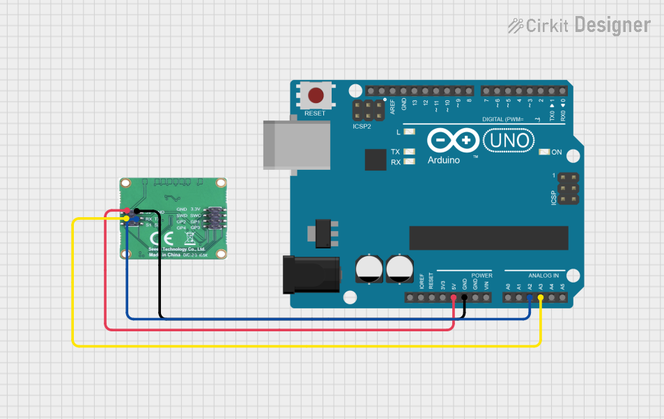
Connecting the SEN0306 to a Circuit

  1. Power Supply: Connect the VCC pin to a 5V DC power source and the GND pin to the ground.
  2. UART Communication: Connect the TX pin of the radar module to the RX pin of your microcontroller (e.g., Arduino UNO). Similarly, connect the RX pin of the radar module to the TX pin of the microcontroller.
  3. Voltage Level: Ensure that the UART communication operates at 3.3V TTL levels. If your microcontroller uses 5V logic (e.g., Arduino UNO), use a level shifter to avoid damaging the module.

Example Code for Arduino UNO

Below is an example Arduino sketch to interface with the SEN0306 module and read radar data via UART:

// Include the SoftwareSerial library for UART communication
#include <SoftwareSerial.h>

// Define the RX and TX pins for the radar module
SoftwareSerial radarSerial(10, 11); // RX = Pin 10, TX = Pin 11

void setup() {
  // Initialize the serial communication for debugging
  Serial.begin(9600);
  // Initialize the radar module communication
  radarSerial.begin(115200); // SEN0306 operates at 115200 baud rate

  Serial.println("SEN0306 Radar Module Initialized");
}

void loop() {
  // Check if data is available from the radar module
  if (radarSerial.available()) {
    // Read and print the data from the radar module
    String radarData = radarSerial.readStringUntil('\n');
    Serial.println("Radar Data: " + radarData);
  }

  delay(100); // Add a small delay to avoid overwhelming the serial buffer
}

Important Considerations

  • Mounting: Ensure the radar module is mounted securely and oriented correctly for optimal detection.
  • Interference: Avoid placing the module near other high-frequency devices to minimize interference.
  • Environment: The module performs best in environments with minimal obstructions and reflective surfaces.

Troubleshooting and FAQs

Common Issues and Solutions

  1. No Data Output

    • Cause: Incorrect wiring or power supply.
    • Solution: Verify the connections, ensuring the VCC and GND pins are properly connected. Check the UART connections and ensure the baud rate is set to 115200.
  2. Inconsistent Readings

    • Cause: Environmental interference or improper mounting.
    • Solution: Ensure the module is mounted securely and away from sources of interference. Test in a controlled environment to verify functionality.
  3. Module Overheating

    • Cause: Excessive current draw or improper power supply.
    • Solution: Use a stable 5V DC power source and ensure the current does not exceed the module's specifications.

FAQs

Q1: Can the SEN0306 detect stationary objects?
A1: Yes, the module can detect stationary objects within its detection range of 0.3 m to 20 m.

Q2: Is the module waterproof?
A2: No, the SEN0306 is not waterproof. If used outdoors, ensure it is housed in a weatherproof enclosure.

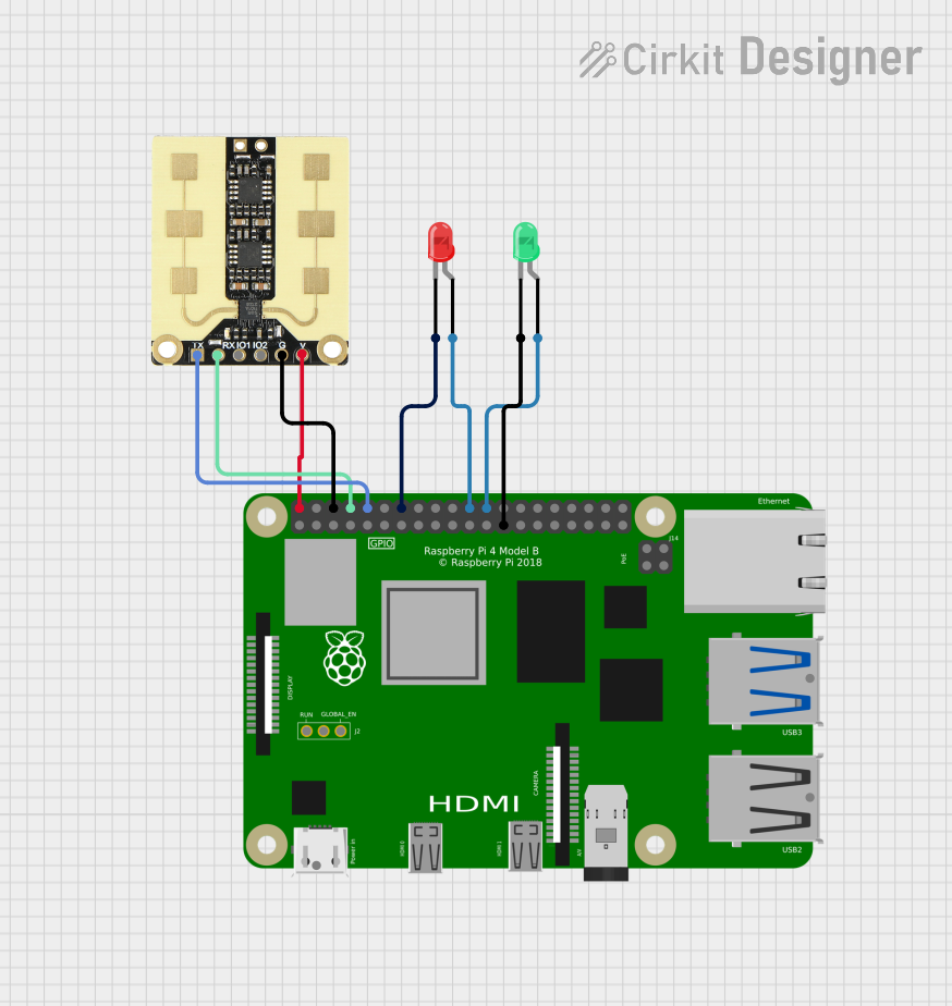
Q3: Can I use the module with a Raspberry Pi?
A3: Yes, the module can be used with a Raspberry Pi. Connect the UART pins to the Raspberry Pi's GPIO pins, ensuring proper voltage levels.

Q4: What is the maximum detection speed?
A4: The module can detect speeds up to ±70 m/s, making it suitable for high-speed applications.

By following this documentation, users can effectively integrate the DFRobot SEN0306 microwave radar module into their projects for reliable object detection and speed sensing.