Cirkit Designer Logo
Cirkit Designer
Your all-in-one circuit design IDE
Home / 
Component Documentation

How to Use relay: Examples, Pinouts, and Specs

Image of relay
Cirkit Designer LogoDesign with relay in Cirkit Designer

Introduction

A relay is an electromechanical switch that uses an electromagnetic coil to open or close a circuit. It allows a low-power signal to control a high-power circuit, making it an essential component in many electronic and electrical systems. Relays are widely used in applications such as home automation, industrial control systems, automotive electronics, and power distribution systems. They provide electrical isolation between the control circuit and the high-power circuit, ensuring safety and reliability.

Explore Projects Built with relay

Use Cirkit Designer to design, explore, and prototype these projects online. Some projects support real-time simulation. Click "Open Project" to start designing instantly!
Arduino-Based Wireless Power Transmission System with Copper Coils
Image of nagesh: A project utilizing relay in a practical application
This circuit consists of multiple copper coils connected to transmitters and a receiver, likely forming a wireless power transfer or communication system. The transmitters are connected to individual coils, and the receiver is connected to another coil, facilitating the transmission and reception of signals or power wirelessly.
Cirkit Designer LogoOpen Project in Cirkit Designer
RF-Controlled Relay Switch with Indicator LEDs and Buzzer
Image of receiver: A project utilizing relay in a practical application
This circuit features an RF receiver that controls a 12V relay, which in turn switches between two circuits: one with a green LED and another with a red LED and a buzzer, both protected by resistors. A rocker switch is used to supply power from a 9V battery to the RF receiver and the relay's coil. The relay's normally closed (NC) contact is connected to the green LED, while the normally open (NO) contact is connected to the red LED and the buzzer, indicating that the relay's state determines which of the two circuits is active.
Cirkit Designer LogoOpen Project in Cirkit Designer
ESP8266 and HC-05 Bluetooth-Based Home Automation System with 4-Channel Relay Control
Image of home automation using arduino: A project utilizing relay in a practical application
This circuit is a Bluetooth-based home automation system that uses an ESP8266 NodeMCU to control a 4-channel relay module. The relays can be toggled via Bluetooth commands received from an HC-05 Bluetooth module or by pressing connected pushbuttons. The system also includes pilot lamps to indicate the status of each relay.
Cirkit Designer LogoOpen Project in Cirkit Designer
Arduino UNO and Relay-Controlled RS485 Communication System
Image of Diagrama: A project utilizing relay in a practical application
This circuit features an Arduino UNO microcontroller interfaced with a 4-channel relay module and a UART TTL to RS485 converter. The Arduino controls the relays via digital pins and communicates with the RS485 converter for serial communication, enabling control of external devices and communication over long distances.
Cirkit Designer LogoOpen Project in Cirkit Designer

Explore Projects Built with relay

Use Cirkit Designer to design, explore, and prototype these projects online. Some projects support real-time simulation. Click "Open Project" to start designing instantly!
Image of nagesh: A project utilizing relay in a practical application
Arduino-Based Wireless Power Transmission System with Copper Coils
This circuit consists of multiple copper coils connected to transmitters and a receiver, likely forming a wireless power transfer or communication system. The transmitters are connected to individual coils, and the receiver is connected to another coil, facilitating the transmission and reception of signals or power wirelessly.
Cirkit Designer LogoOpen Project in Cirkit Designer
Image of receiver: A project utilizing relay in a practical application
RF-Controlled Relay Switch with Indicator LEDs and Buzzer
This circuit features an RF receiver that controls a 12V relay, which in turn switches between two circuits: one with a green LED and another with a red LED and a buzzer, both protected by resistors. A rocker switch is used to supply power from a 9V battery to the RF receiver and the relay's coil. The relay's normally closed (NC) contact is connected to the green LED, while the normally open (NO) contact is connected to the red LED and the buzzer, indicating that the relay's state determines which of the two circuits is active.
Cirkit Designer LogoOpen Project in Cirkit Designer
Image of home automation using arduino: A project utilizing relay in a practical application
ESP8266 and HC-05 Bluetooth-Based Home Automation System with 4-Channel Relay Control
This circuit is a Bluetooth-based home automation system that uses an ESP8266 NodeMCU to control a 4-channel relay module. The relays can be toggled via Bluetooth commands received from an HC-05 Bluetooth module or by pressing connected pushbuttons. The system also includes pilot lamps to indicate the status of each relay.
Cirkit Designer LogoOpen Project in Cirkit Designer
Image of Diagrama: A project utilizing relay in a practical application
Arduino UNO and Relay-Controlled RS485 Communication System
This circuit features an Arduino UNO microcontroller interfaced with a 4-channel relay module and a UART TTL to RS485 converter. The Arduino controls the relays via digital pins and communicates with the RS485 converter for serial communication, enabling control of external devices and communication over long distances.
Cirkit Designer LogoOpen Project in Cirkit Designer

Technical Specifications

Below are the general technical specifications for a standard single-pole single-throw (SPST) relay. Specifications may vary depending on the specific relay model.

General Specifications

  • Coil Voltage: 5V, 12V, or 24V DC (common values)
  • Coil Current: Typically 30-100 mA
  • Contact Rating: 10A at 250V AC or 10A at 30V DC
  • Contact Type: SPST (Single Pole Single Throw) or SPDT (Single Pole Double Throw)
  • Switching Time: 5-15 ms (typical)
  • Dielectric Strength: 1000V AC (between coil and contacts)
  • Insulation Resistance: >100 MΩ at 500V DC
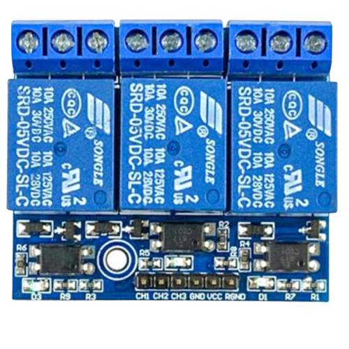
Pin Configuration

The pin configuration of a typical 5V SPDT relay is as follows:

Pin Name Description
Coil+ Positive terminal of the electromagnetic coil.
Coil- Negative terminal of the electromagnetic coil.
COM Common terminal for the relay switch.
NO Normally Open terminal. Connected to COM when the relay is activated.
NC Normally Closed terminal. Connected to COM when the relay is not activated.
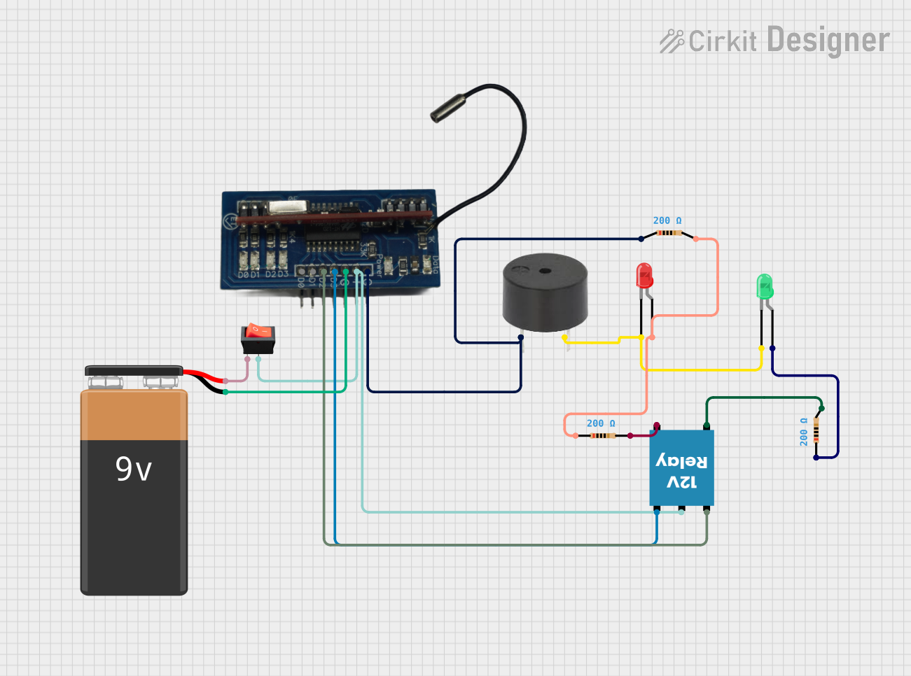
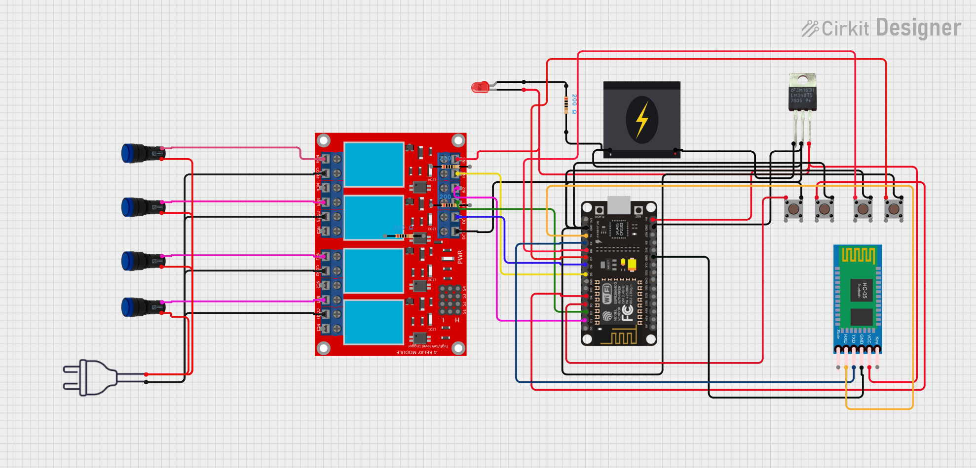
Usage Instructions

How to Use a Relay in a Circuit

  1. Power the Coil: Connect the relay's coil terminals (Coil+ and Coil-) to a low-power control circuit, such as a microcontroller or a transistor driver circuit. Ensure the coil voltage matches the relay's rated voltage.
  2. Connect the Load: Wire the high-power circuit to the relay's COM and NO (or NC) terminals, depending on whether you want the circuit to be normally open or normally closed.
  3. Control the Relay: Use a control signal (e.g., from an Arduino or other microcontroller) to energize the coil, which will switch the relay and control the high-power circuit.

Important Considerations

  • Flyback Diode: Always connect a flyback diode across the relay coil to protect the control circuit from voltage spikes caused by the collapsing magnetic field when the relay is turned off.
  • Current Rating: Ensure the relay's contact rating is sufficient for the load current.
  • Isolation: Use optocouplers or other isolation techniques if the control circuit and high-power circuit operate at different voltage levels.

Example: Connecting a Relay to an Arduino UNO

Below is an example of how to control a 5V relay using an Arduino UNO:

// Define the pin connected to the relay module
const int relayPin = 7;

void setup() {
  pinMode(relayPin, OUTPUT); // Set the relay pin as an output
  digitalWrite(relayPin, LOW); // Ensure the relay is off at startup
}

void loop() {
  digitalWrite(relayPin, HIGH); // Turn the relay on
  delay(1000); // Keep the relay on for 1 second
  digitalWrite(relayPin, LOW); // Turn the relay off
  delay(1000); // Keep the relay off for 1 second
}

Note: Ensure the relay module is connected to the Arduino's ground (GND) and the relay's control pin is connected to the specified relayPin.

Troubleshooting and FAQs

Common Issues

  1. Relay Not Switching:

    • Cause: Insufficient voltage or current to the coil.
    • Solution: Verify the control circuit provides the correct voltage and current for the relay.
  2. Chattering or Buzzing Noise:

    • Cause: Unstable control signal or insufficient power supply.
    • Solution: Use a stable power source and ensure the control signal is steady.
  3. Load Not Turning On/Off:

    • Cause: Incorrect wiring of the load to the relay terminals.
    • Solution: Double-check the connections to the COM, NO, and NC terminals.
  4. Microcontroller Resetting When Relay Activates:

    • Cause: Voltage spikes from the relay coil affecting the microcontroller.
    • Solution: Add a flyback diode across the relay coil and ensure proper decoupling capacitors are used in the circuit.

FAQs

  • Q: Can I use a relay to switch AC loads?

    • A: Yes, relays are commonly used to switch AC loads. Ensure the relay's contact rating supports the voltage and current of the AC load.
  • Q: What is the purpose of the flyback diode?

    • A: The flyback diode protects the control circuit from voltage spikes generated when the relay coil is de-energized.
  • Q: Can I control a relay directly from a microcontroller pin?

    • A: Most microcontroller pins cannot supply enough current to drive a relay directly. Use a transistor or relay driver circuit to control the relay.
  • Q: How do I choose the right relay for my application?

    • A: Consider the coil voltage, contact rating, switching time, and physical size of the relay. Ensure it meets the requirements of your control and load circuits.