
How to Use LM339 Quad Comparator: Examples, Pinouts, and Specs
 Design with LM339 Quad Comparator in Cirkit Designer
Introduction
The LM339 Quad Comparator is a versatile electronic component featuring four independent, high-speed voltage comparators. Manufactured by local, this device is designed to operate from a single power supply, making it ideal for a wide range of applications. The LM339 is commonly used in circuits requiring voltage level detection, signal conditioning, and analog-to-digital conversion. Its ability to handle low power consumption and wide voltage ranges makes it a popular choice in both industrial and consumer electronics.
Explore Projects Built with LM339 Quad Comparator
 Open Project in Cirkit Designer
 Open Project in Cirkit Designer
 Open Project in Cirkit Designer
 Open Project in Cirkit Designer
Explore Projects Built with LM339 Quad Comparator
Open Project in Cirkit DesignerOpen Project in Cirkit DesignerOpen Project in Cirkit DesignerOpen Project in Cirkit DesignerCommon Applications
- Zero-crossing detectors
- Voltage level detection
- Pulse-width modulation (PWM) circuits
- Analog-to-digital conversion (ADC) circuits
- Signal conditioning in sensor systems
- Oscillators and waveform generators
Technical Specifications
The LM339 Quad Comparator is designed to meet the needs of various applications with the following key specifications:
| Parameter | Value |
|---|---|
| Manufacturer | local |
| Part ID | LM339 Quad Comparator |
| Number of Comparators | 4 |
| Supply Voltage Range | 2V to 36V (single supply) |
| Input Offset Voltage | 2mV (typical) |
| Input Common-Mode Voltage | 0V to (Vcc - 2V) |
| Output Voltage Range | 0V to 36V |
| Output Sink Current | 16mA (maximum) |
| Operating Temperature Range | -40°C to +85°C |
| Package Types | DIP-14, SOIC-14, TSSOP-14 |
Pin Configuration and Descriptions
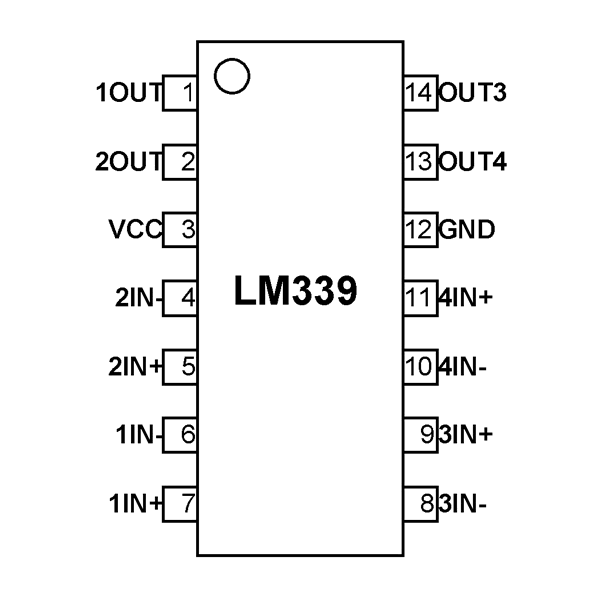
The LM339 is typically available in a 14-pin package. Below is the pinout and description:
| Pin Number | Pin Name | Description |
|---|---|---|
| 1 | OUT1 | Output of Comparator 1 |
| 2 | IN1- | Inverting Input of Comparator 1 |
| 3 | IN1+ | Non-Inverting Input of Comparator 1 |
| 4 | VCC | Positive Power Supply |
| 5 | IN2+ | Non-Inverting Input of Comparator 2 |
| 6 | IN2- | Inverting Input of Comparator 2 |
| 7 | OUT2 | Output of Comparator 2 |
| 8 | OUT3 | Output of Comparator 3 |
| 9 | IN3- | Inverting Input of Comparator 3 |
| 10 | IN3+ | Non-Inverting Input of Comparator 3 |
| 11 | GND | Ground (0V) |
| 12 | IN4+ | Non-Inverting Input of Comparator 4 |
| 13 | IN4- | Inverting Input of Comparator 4 |
| 14 | OUT4 | Output of Comparator 4 |
Usage Instructions
How to Use the LM339 in a Circuit
- Power Supply: Connect the VCC pin (Pin 4) to a positive voltage source (2V to 36V) and the GND pin (Pin 11) to ground.
- Inputs: Provide the input signals to the inverting (IN-) and non-inverting (IN+) pins of the desired comparator(s). Ensure the input voltage stays within the common-mode range (0V to VCC - 2V).
- Outputs: The output pins (OUT1 to OUT4) are open-collector, meaning they require a pull-up resistor to function correctly. Connect a resistor (typically 10kΩ) between the output pin and the positive supply voltage.
- Load: The output can sink current up to 16mA, so ensure the connected load does not exceed this limit.
Important Considerations
- Pull-Up Resistors: Always use pull-up resistors on the output pins to ensure proper operation.
- Input Voltage Range: Avoid exceeding the input voltage range to prevent damage or incorrect operation.
- Bypass Capacitor: Place a decoupling capacitor (e.g., 0.1µF) close to the VCC pin to reduce noise and improve stability.
- Unused Comparators: If any comparator is unused, connect its inputs to ground or VCC to avoid floating inputs.
Example: Connecting LM339 to an Arduino UNO
The LM339 can be used with an Arduino UNO for voltage level detection. Below is an example circuit and code:
Circuit Description
- Connect the VCC pin of the LM339 to the Arduino's 5V pin and the GND pin to the Arduino's GND.
- Use one comparator to monitor a voltage signal. Connect the signal to the non-inverting input (IN1+), and connect a reference voltage (e.g., from a voltage divider) to the inverting input (IN1-).
- Connect the output (OUT1) to a digital input pin on the Arduino (e.g., D2) with a pull-up resistor.
Arduino Code
// LM339 Comparator Example with Arduino UNO
// This code reads the output of the LM339 and turns on an LED if the signal
// exceeds the reference voltage.

const int comparatorOutputPin = 2; // LM339 output connected to digital pin 2
const int ledPin = 13;             // Onboard LED pin

void setup() {
  pinMode(comparatorOutputPin, INPUT); // Set comparator output as input
  pinMode(ledPin, OUTPUT);            // Set LED pin as output
}

void loop() {
  int comparatorState = digitalRead(comparatorOutputPin); // Read LM339 output

  if (comparatorState == HIGH) {
    digitalWrite(ledPin, HIGH); // Turn on LED if signal is above reference
  } else {
    digitalWrite(ledPin, LOW);  // Turn off LED otherwise
  }
}
Troubleshooting and FAQs
Common Issues
No Output Signal:
- Ensure pull-up resistors are connected to the output pins.
- Verify that the input signals are within the specified voltage range.
Incorrect Output Behavior:
- Check the polarity of the input signals (IN+ and IN-).
- Ensure the reference voltage is correctly set.
Noise or Instability:
- Add a bypass capacitor (0.1µF) near the VCC pin to reduce noise.
- Verify that the power supply is stable and free of fluctuations.
Overheating:
- Ensure the load connected to the output does not exceed the maximum sink current (16mA).
FAQs
Q: Can the LM339 operate with a dual power supply?
A: Yes, the LM339 can operate with a dual power supply (e.g., ±15V). In this case, the GND pin (Pin 11) should be connected to the negative supply.
Q: What happens if I leave unused comparators floating?
A: Floating inputs can cause unpredictable behavior. Always connect unused inputs to a fixed voltage (e.g., ground or VCC).
Q: Can the LM339 drive LEDs directly?
A: Yes, but ensure the LED current does not exceed 16mA. Use a current-limiting resistor in series with the LED.
Q: Is the LM339 suitable for high-frequency applications?
A: The LM339 is not designed for high-frequency applications. It is best suited for low- to mid-frequency signals.