Cirkit Designer Logo
Cirkit Designer
Your all-in-one circuit design IDE
Home / 
Component Documentation

How to Use Vibration sensor module alarm Motion sensor module vibration switch SW-420: Examples, Pinouts, and Specs

Image of Vibration sensor module alarm Motion sensor module vibration switch SW-420
Cirkit Designer LogoDesign with Vibration sensor module alarm Motion sensor module vibration switch SW-420 in Cirkit Designer

Introduction

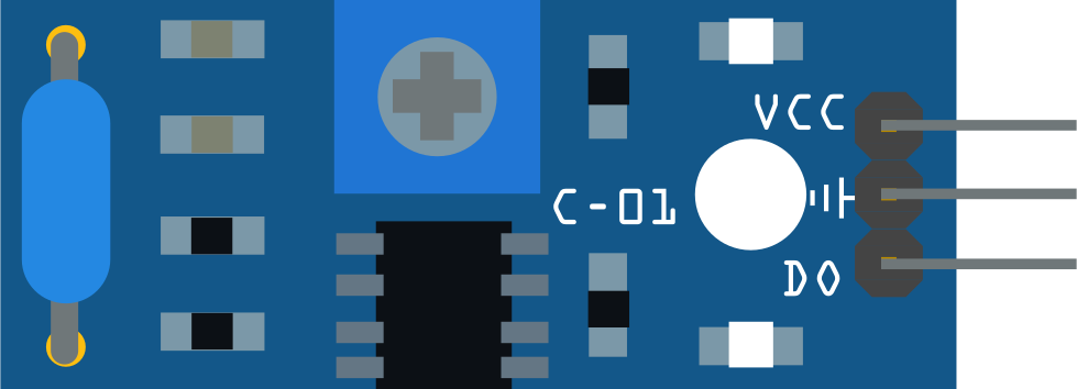
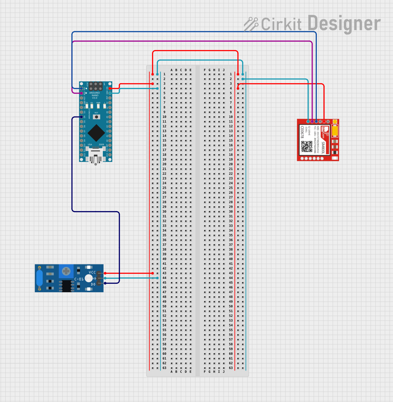
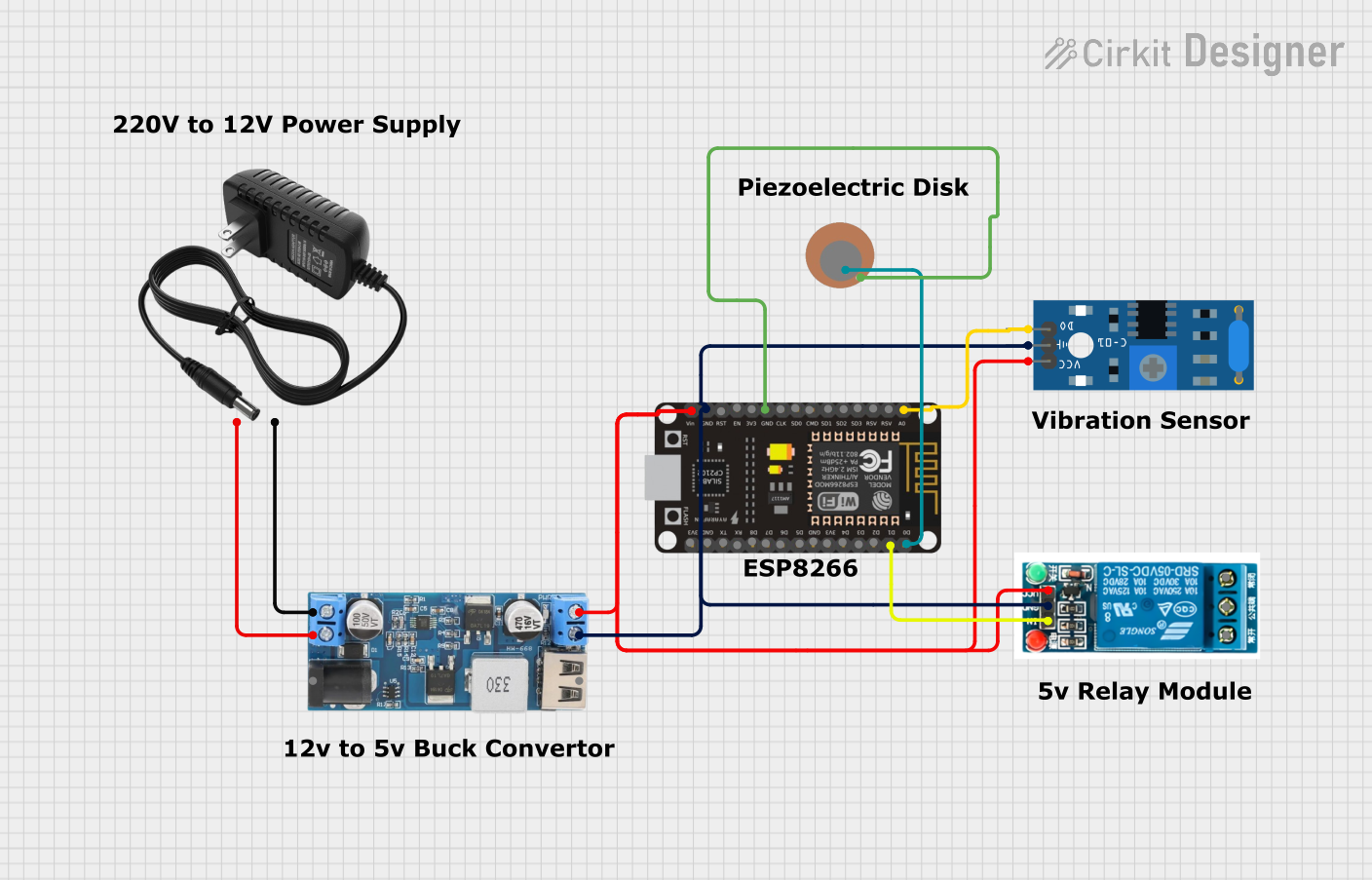
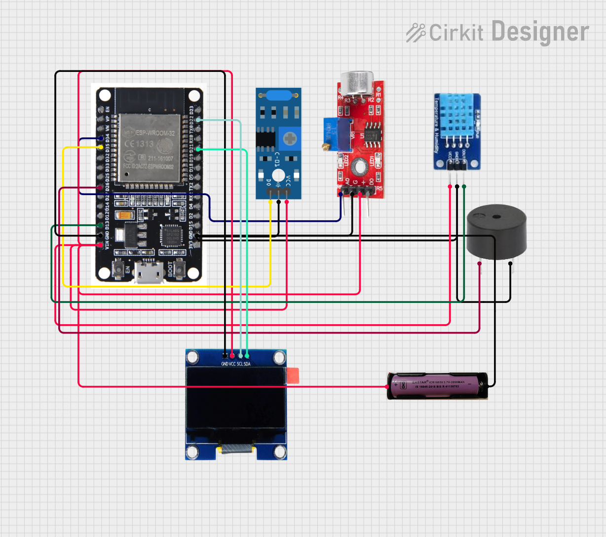
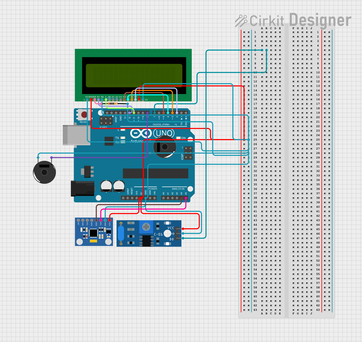
The SW-420 Vibration Sensor Module is a compact and reliable electronic component designed to detect vibrations or shocks in its environment. It is equipped with an SW-420 vibration switch and a comparator circuit to provide a digital output signal when vibrations exceed a certain threshold. This module is widely used in security systems, vibration alarms, and motion detection applications.

Explore Projects Built with Vibration sensor module alarm Motion sensor module vibration switch SW-420

Use Cirkit Designer to design, explore, and prototype these projects online. Some projects support real-time simulation. Click "Open Project" to start designing instantly!
Arduino Nano-Based Vibration Detection System with SIM800L GSM Module
Image of asd: A project utilizing Vibration sensor module alarm Motion sensor module vibration switch SW-420 in a practical application
This circuit is designed to detect vibrations using the SW-420 Vibration Sensor and communicate the detection events via the Sim800l GSM module. The Arduino Nano serves as the central controller, interfacing with the vibration sensor on its digital pin D4 and with the Sim800l module through serial communication using pins D0/RX and D1/TX. The circuit is likely intended for remote monitoring of vibrations, potentially for security or machinery fault detection applications.
Cirkit Designer LogoOpen Project in Cirkit Designer
Wi-Fi Controlled Vibration and Piezo Sensor System with ESP8266 and Relay
Image of Smart Airbag: A project utilizing Vibration sensor module alarm Motion sensor module vibration switch SW-420 in a practical application
This circuit is a vibration detection system that uses an SW-420 vibration sensor and a piezo sensor to detect vibrations and trigger a 5V relay. The system is controlled by an ESP8266 NodeMCU, which processes the sensor inputs and controls the relay. A 12V power supply is stepped down to 5V to power the components.
Cirkit Designer LogoOpen Project in Cirkit Designer
ESP32-Based Environmental Monitoring System with Vibration and Sound Detection
Image of DRONE CIRCUIT: A project utilizing Vibration sensor module alarm Motion sensor module vibration switch SW-420 in a practical application
This circuit features an ESP32 microcontroller connected to various sensors and output devices. A sound sensor and a SW-420 vibration sensor provide analog and digital inputs, respectively, to the ESP32 for environmental monitoring. The circuit also includes a DHT11 sensor for temperature and humidity readings, a buzzer for audible alerts, and an OLED display for visual feedback, all interfaced with the ESP32. Power is supplied by a 3.7V source connected to all components requiring VCC.
Cirkit Designer LogoOpen Project in Cirkit Designer
Arduino-Based Vibration and Motion Detection System with LCD Display
Image of blueprint: A project utilizing Vibration sensor module alarm Motion sensor module vibration switch SW-420 in a practical application
This circuit uses an Arduino UNO to interface with an SW-420 vibration sensor, an MPU6050 accelerometer and gyroscope, a 16x2 LCD display, and a piezo buzzer. The Arduino reads data from the sensors and displays relevant information on the LCD, while the piezo buzzer provides audible alerts based on sensor inputs.
Cirkit Designer LogoOpen Project in Cirkit Designer

Explore Projects Built with Vibration sensor module alarm Motion sensor module vibration switch SW-420

Use Cirkit Designer to design, explore, and prototype these projects online. Some projects support real-time simulation. Click "Open Project" to start designing instantly!
Image of asd: A project utilizing Vibration sensor module alarm Motion sensor module vibration switch SW-420 in a practical application
Arduino Nano-Based Vibration Detection System with SIM800L GSM Module
This circuit is designed to detect vibrations using the SW-420 Vibration Sensor and communicate the detection events via the Sim800l GSM module. The Arduino Nano serves as the central controller, interfacing with the vibration sensor on its digital pin D4 and with the Sim800l module through serial communication using pins D0/RX and D1/TX. The circuit is likely intended for remote monitoring of vibrations, potentially for security or machinery fault detection applications.
Cirkit Designer LogoOpen Project in Cirkit Designer
Image of Smart Airbag: A project utilizing Vibration sensor module alarm Motion sensor module vibration switch SW-420 in a practical application
Wi-Fi Controlled Vibration and Piezo Sensor System with ESP8266 and Relay
This circuit is a vibration detection system that uses an SW-420 vibration sensor and a piezo sensor to detect vibrations and trigger a 5V relay. The system is controlled by an ESP8266 NodeMCU, which processes the sensor inputs and controls the relay. A 12V power supply is stepped down to 5V to power the components.
Cirkit Designer LogoOpen Project in Cirkit Designer
Image of DRONE CIRCUIT: A project utilizing Vibration sensor module alarm Motion sensor module vibration switch SW-420 in a practical application
ESP32-Based Environmental Monitoring System with Vibration and Sound Detection
This circuit features an ESP32 microcontroller connected to various sensors and output devices. A sound sensor and a SW-420 vibration sensor provide analog and digital inputs, respectively, to the ESP32 for environmental monitoring. The circuit also includes a DHT11 sensor for temperature and humidity readings, a buzzer for audible alerts, and an OLED display for visual feedback, all interfaced with the ESP32. Power is supplied by a 3.7V source connected to all components requiring VCC.
Cirkit Designer LogoOpen Project in Cirkit Designer
Image of blueprint: A project utilizing Vibration sensor module alarm Motion sensor module vibration switch SW-420 in a practical application
Arduino-Based Vibration and Motion Detection System with LCD Display
This circuit uses an Arduino UNO to interface with an SW-420 vibration sensor, an MPU6050 accelerometer and gyroscope, a 16x2 LCD display, and a piezo buzzer. The Arduino reads data from the sensors and displays relevant information on the LCD, while the piezo buzzer provides audible alerts based on sensor inputs.
Cirkit Designer LogoOpen Project in Cirkit Designer

Common Applications and Use Cases

  • Anti-theft alarm systems
  • Earthquake detection devices
  • Smart home automation
  • Industrial equipment monitoring
  • Motion-triggered lighting systems

Technical Specifications

The SW-420 Vibration Sensor Module has the following key specifications:

Parameter Value
Operating Voltage 3.3V to 5V
Output Type Digital (High/Low)
Sensitivity Adjustment Via onboard potentiometer
Dimensions 32mm x 14mm x 8mm
Output Signal High (no vibration), Low (vibration detected)
Operating Temperature -40°C to +85°C

Pin Configuration and Descriptions

The module has a 3-pin interface:

Pin Name Description
1 VCC Power supply input (3.3V to 5V)
2 GND Ground connection
3 DO Digital output signal (High/Low based on vibration)

Usage Instructions

How to Use the Component in a Circuit

  1. Power the Module: Connect the VCC pin to a 3.3V or 5V power source and the GND pin to the ground of your circuit.
  2. Connect the Output: Use the DO pin to read the digital output signal. This pin will output a HIGH signal when no vibration is detected and a LOW signal when vibration is detected.
  3. Adjust Sensitivity: Use the onboard potentiometer to adjust the sensitivity of the vibration detection. Turning the potentiometer clockwise increases sensitivity, while turning it counterclockwise decreases sensitivity.
  4. Integrate with a Microcontroller: Connect the DO pin to a digital input pin of a microcontroller (e.g., Arduino UNO) to process the vibration signal.

Important Considerations and Best Practices

  • Ensure the module is securely mounted to avoid false triggers caused by loose connections.
  • Avoid placing the module near strong electromagnetic interference sources, as this may affect its performance.
  • Use appropriate pull-up or pull-down resistors if required by your circuit design.
  • For long-term reliability, avoid exposing the module to extreme temperatures or humidity.

Example Code for Arduino UNO

The following code demonstrates how to use the SW-420 Vibration Sensor Module with an Arduino UNO to detect vibrations and trigger an LED:

// Define the pin connections
const int vibrationPin = 2; // Digital pin connected to the DO pin of the module
const int ledPin = 13;      // Built-in LED pin on Arduino UNO

void setup() {
  pinMode(vibrationPin, INPUT); // Set the vibration sensor pin as input
  pinMode(ledPin, OUTPUT);      // Set the LED pin as output
  Serial.begin(9600);           // Initialize serial communication for debugging
}

void loop() {
  int vibrationState = digitalRead(vibrationPin); // Read the sensor output

  if (vibrationState == LOW) {
    // If vibration is detected, turn on the LED
    digitalWrite(ledPin, HIGH);
    Serial.println("Vibration detected!");
  } else {
    // If no vibration is detected, turn off the LED
    digitalWrite(ledPin, LOW);
    Serial.println("No vibration.");
  }

  delay(100); // Add a small delay to stabilize readings
}

Troubleshooting and FAQs

Common Issues and Solutions

  1. No Output Signal Detected

    • Solution: Verify the power connections to the module. Ensure the VCC and GND pins are properly connected to the power supply.
    • Solution: Check the sensitivity setting on the potentiometer. Increase the sensitivity if necessary.
  2. False Triggers

    • Solution: Ensure the module is securely mounted to avoid unintended vibrations.
    • Solution: Reduce the sensitivity using the potentiometer to filter out minor vibrations.
  3. Output Signal Always HIGH

    • Solution: Verify that the module is not in a completely vibration-free environment. Test by gently tapping the module.
    • Solution: Check the DO pin connection to the microcontroller or circuit.
  4. Output Signal Always LOW

    • Solution: Ensure the module is not exposed to constant vibrations. Test by isolating the module from external motion.
    • Solution: Inspect the module for physical damage or loose components.

FAQs

Q: Can the SW-420 module detect very small vibrations?
A: Yes, the sensitivity can be adjusted using the onboard potentiometer to detect even small vibrations.

Q: Is the module compatible with 3.3V systems?
A: Yes, the module operates within a voltage range of 3.3V to 5V, making it compatible with both 3.3V and 5V systems.

Q: Can I use multiple SW-420 modules in the same circuit?
A: Yes, multiple modules can be used, but ensure each module is properly powered and connected to separate input pins on the microcontroller.

Q: How do I know if the module is working?
A: The onboard LED will light up when vibration is detected, providing a visual indication of the module's operation.