Cirkit Designer Logo
Cirkit Designer
Your all-in-one circuit design IDE
Home / 
Component Documentation

How to Use STM32U083C-DK: Examples, Pinouts, and Specs

Image of STM32U083C-DK
Cirkit Designer LogoDesign with STM32U083C-DK in Cirkit Designer

Introduction

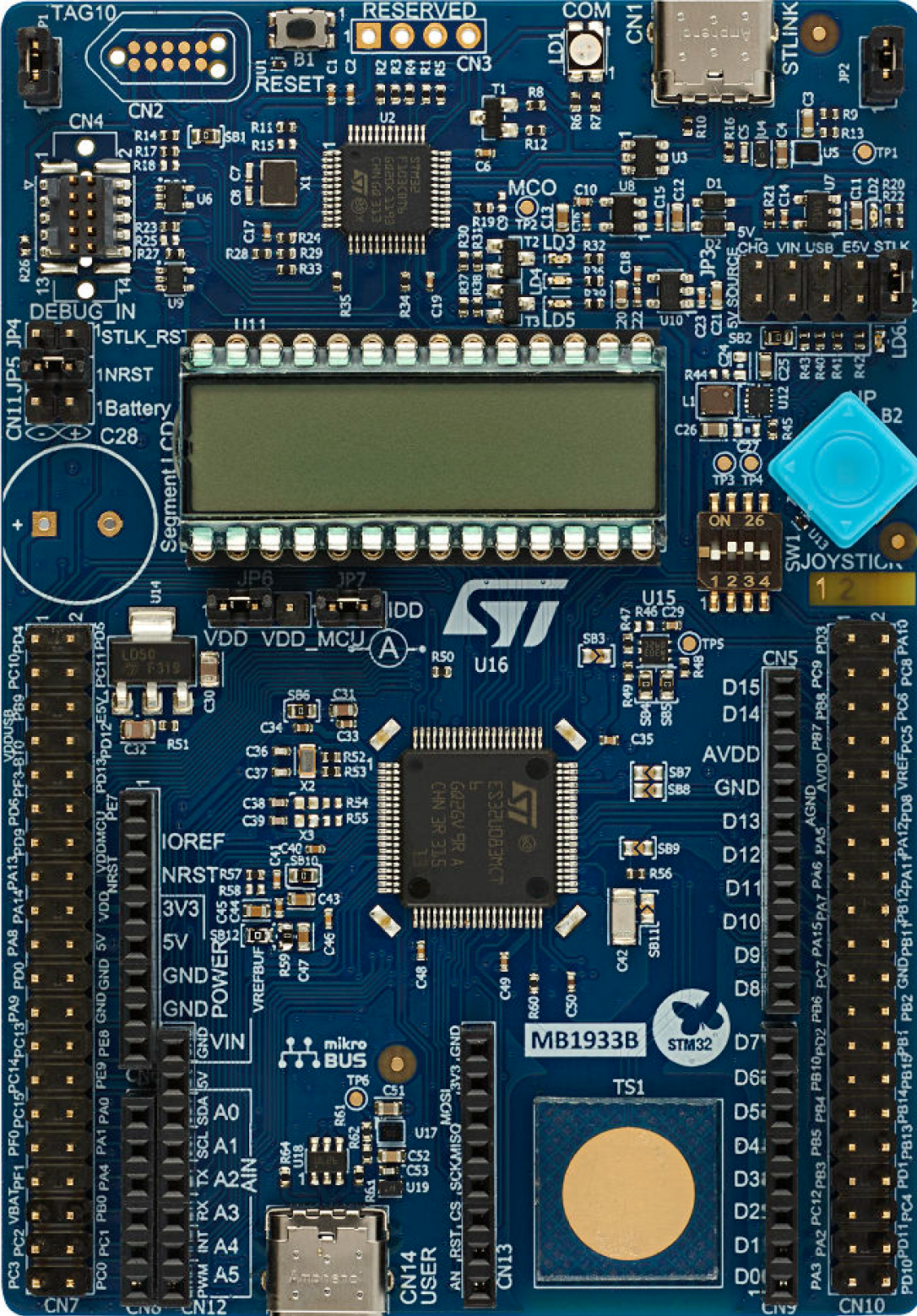
The STM32U083C-DK Development Kit is a comprehensive platform for prototyping and evaluating the STM32U083C microcontroller from ST Microelectronics. This microcontroller is part of the STM32 family, which is renowned for its high performance, low power consumption, and advanced features. The development kit is ideal for a wide range of applications, including industrial control, consumer electronics, and Internet of Things (IoT) devices.

Explore Projects Built with STM32U083C-DK

Use Cirkit Designer to design, explore, and prototype these projects online. Some projects support real-time simulation. Click "Open Project" to start designing instantly!
STM32F103C8T6-Based Spectral Sensor with ST7735S Display and Pushbutton Control
Image of ColorSensor: A project utilizing STM32U083C-DK in a practical application
This circuit features an STM32F103C8T6 microcontroller interfaced with a China ST7735S 160x128 display and two spectral sensors (Adafruit AS7262 and AS7261). It also includes two pushbuttons for user input, with the microcontroller managing the display and sensor data processing.
Cirkit Designer LogoOpen Project in Cirkit Designer
Solar-Powered STM32-Based Automation System with Matrix Keypad and RTC
Image of soloar cleaner : A project utilizing STM32U083C-DK in a practical application
This circuit features an STM32F103C8T6 microcontroller interfaced with a membrane matrix keypad for input, an RTC DS3231 for real-time clock functionality, and a 16x2 I2C LCD for display. It controls four 12V geared motors through two MD20 CYTRON motor drivers, with the motor power supplied by a 12V battery regulated by a buck converter. The battery is charged via a solar panel connected through a solar charge controller, ensuring a renewable energy source for the system.
Cirkit Designer LogoOpen Project in Cirkit Designer
STM32F103C8T6 Microcontroller-Based Motor Control System with RS485 Communication
Image of ROBOCON_TASK 1 SCHME DIAGRAM: A project utilizing STM32U083C-DK in a practical application
This circuit is designed to control LEDs, a DC motor, and a servo motor using an STM32F103C8T6 microcontroller. It includes a motor driver for the DC motor, a voltage regulator for stable power supply, and an RS485 to USB converter for communication. User inputs can be provided through pushbuttons, and a potentiometer allows for variable analog input.
Cirkit Designer LogoOpen Project in Cirkit Designer
STM32 Nucleo F303RE Controlled Ultrasonic Sensing with RGB Feedback and I2C LCD Display
Image of CS435-final: A project utilizing STM32U083C-DK in a practical application
This circuit features a STM32 Nucleo F303RE microcontroller interfaced with three HC-SR04 ultrasonic sensors for distance measurement and a 20x4 LCD display over I2C for data output. Additionally, there is a WS2812 RGB LED strip controlled by the microcontroller for visual feedback. The power supply provides a common 5V to the LCD, ultrasonic sensors, LED strip, and the microcontroller's +5V input, with all components sharing a common ground.
Cirkit Designer LogoOpen Project in Cirkit Designer

Explore Projects Built with STM32U083C-DK

Use Cirkit Designer to design, explore, and prototype these projects online. Some projects support real-time simulation. Click "Open Project" to start designing instantly!
Image of ColorSensor: A project utilizing STM32U083C-DK in a practical application
STM32F103C8T6-Based Spectral Sensor with ST7735S Display and Pushbutton Control
This circuit features an STM32F103C8T6 microcontroller interfaced with a China ST7735S 160x128 display and two spectral sensors (Adafruit AS7262 and AS7261). It also includes two pushbuttons for user input, with the microcontroller managing the display and sensor data processing.
Cirkit Designer LogoOpen Project in Cirkit Designer
Image of soloar cleaner : A project utilizing STM32U083C-DK in a practical application
Solar-Powered STM32-Based Automation System with Matrix Keypad and RTC
This circuit features an STM32F103C8T6 microcontroller interfaced with a membrane matrix keypad for input, an RTC DS3231 for real-time clock functionality, and a 16x2 I2C LCD for display. It controls four 12V geared motors through two MD20 CYTRON motor drivers, with the motor power supplied by a 12V battery regulated by a buck converter. The battery is charged via a solar panel connected through a solar charge controller, ensuring a renewable energy source for the system.
Cirkit Designer LogoOpen Project in Cirkit Designer
Image of ROBOCON_TASK 1 SCHME DIAGRAM: A project utilizing STM32U083C-DK in a practical application
STM32F103C8T6 Microcontroller-Based Motor Control System with RS485 Communication
This circuit is designed to control LEDs, a DC motor, and a servo motor using an STM32F103C8T6 microcontroller. It includes a motor driver for the DC motor, a voltage regulator for stable power supply, and an RS485 to USB converter for communication. User inputs can be provided through pushbuttons, and a potentiometer allows for variable analog input.
Cirkit Designer LogoOpen Project in Cirkit Designer
Image of CS435-final: A project utilizing STM32U083C-DK in a practical application
STM32 Nucleo F303RE Controlled Ultrasonic Sensing with RGB Feedback and I2C LCD Display
This circuit features a STM32 Nucleo F303RE microcontroller interfaced with three HC-SR04 ultrasonic sensors for distance measurement and a 20x4 LCD display over I2C for data output. Additionally, there is a WS2812 RGB LED strip controlled by the microcontroller for visual feedback. The power supply provides a common 5V to the LCD, ultrasonic sensors, LED strip, and the microcontroller's +5V input, with all components sharing a common ground.
Cirkit Designer LogoOpen Project in Cirkit Designer

Technical Specifications

Key Technical Details

  • Microcontroller: STM32U083C
  • Core: ARM Cortex-M0+
  • Operating Voltage: 1.8V to 3.6V
  • Flash Memory: 64 KB
  • SRAM: 8 KB
  • Clock Frequency: Up to 64 MHz
  • Analog-to-Digital Converter (ADC): 12-bit resolution
  • Digital-to-Analog Converter (DAC): 12-bit resolution
  • Communication Interfaces: I2C, SPI, UART, USB
  • Debugging: On-board ST-LINK/V2-1 debugger/programmer

Pin Configuration and Descriptions

Pin Number Pin Name Description
1 VDD Power supply voltage
2 VSS Ground reference
3-6 PA0-PA3 GPIO/ADC/DAC/Timers
7-10 PB0-PB3 GPIO/ADC/Timers/Communication interfaces
... ... ...
N RESET Reset input

Note: This is a simplified representation. The actual development kit has many more pins, each with multiple functions.

Usage Instructions

Integrating the STM32U083C-DK into a Circuit

  1. Power Supply: Connect a stable power source to the VDD pins and ground to the VSS pins.
  2. Programming: Use the on-board ST-LINK/V2-1 for programming the microcontroller via USB.
  3. Peripheral Connections: Connect peripherals to the appropriate GPIO pins, taking into account the pin's supported functions.
  4. Clock Configuration: Configure the system clock source and frequency using the internal or external oscillators.

Important Considerations and Best Practices

  • ESD Precautions: Always handle the development kit with proper electrostatic discharge (ESD) precautions.
  • Power Sequencing: Ensure that the power supply is stable and within the specified voltage range before powering up the kit.
  • Firmware Development: Use the STM32CubeIDE or other compatible development environments for firmware development.
  • Pin Multiplexing: Refer to the microcontroller's datasheet for detailed information on pin multiplexing and alternate functions.

Troubleshooting and FAQs

Common Issues

  • Power Issues: If the development kit does not power on, check the power supply connections and voltage levels.
  • Programming Errors: Ensure that the correct drivers for the ST-LINK/V2-1 are installed and that the USB connection is secure.
  • Peripheral Malfunction: Verify that the peripheral is connected to the correct pins and that the pin configuration in the firmware matches the hardware setup.

Solutions and Tips

  • Driver Installation: Download and install the latest ST-LINK drivers from the ST Microelectronics website.
  • Firmware Debugging: Use the debugging features of the STM32CubeIDE to step through the code and identify issues.
  • Consult Documentation: Refer to the STM32U083C microcontroller datasheet for detailed information on its features and capabilities.

FAQs

Q: Can I use the STM32U083C-DK with an Arduino UNO? A: The STM32U083C-DK is not directly compatible with the Arduino UNO form factor, but you can use it alongside an Arduino UNO by connecting the two via communication interfaces such as UART, SPI, or I2C.

Q: What software do I need to develop for the STM32U083C-DK? A: You can use STM32CubeIDE, which is an all-in-one development platform provided by ST Microelectronics, or other compatible ARM development tools.

Q: How do I update the firmware on the ST-LINK/V2-1 debugger/programmer? A: Firmware updates for the ST-LINK/V2-1 can be obtained from the ST Microelectronics website and uploaded using the ST-LINK Utility software.

Example Code for Arduino UNO Communication

// Example code for STM32U083C-DK communicating with Arduino UNO via UART
#include "stm32u0xx_hal.h"

// Initialize UART peripheral (pseudo-code, replace with actual initialization)
void init_UART(void) {
    // UART initialization code specific to STM32U083C-DK
}

// Send data to Arduino UNO (pseudo-code, replace with actual send function)
void UART_SendData(uint8_t* data, uint16_t size) {
    // Code to send data over UART
}

int main(void) {
    // Initialize hardware and UART
    HAL_Init();
    init_UART();

    // Data to send to Arduino UNO
    uint8_t message[] = "Hello, Arduino UNO!";

    // Send data
    UART_SendData(message, sizeof(message));

    // Main loop
    while (1) {
        // Application code
    }
}

Note: The above code is a simplified example to illustrate UART communication. Actual implementation will require proper initialization and configuration of the UART peripheral, as well as handling of data reception and error conditions.

This documentation provides a starting point for working with the STM32U083C-DK Development Kit. For more detailed information, consult the STM32U083C microcontroller datasheet and the development kit user manual.