How to Use Adafruit RFM9x LoRa Radio: Examples, Pinouts, and Specs
Introduction
The Adafruit RFM9x LoRa Radio is a powerful wireless module that leverages the capabilities of the Semtech SX127x LoRa (Long Range) transceiver, enabling long-distance communication with low power consumption. This module operates in the ISM (Industrial, Scientific, and Medical) bands, which include 433 MHz, 868 MHz, and 915 MHz frequencies, making it versatile for a wide range of applications. It is commonly used in remote sensing, Internet of Things (IoT) applications, and wireless data transfer scenarios where traditional Wi-Fi or Bluetooth connections are impractical due to range limitations or power constraints.
Explore Projects Built with Adafruit RFM9x LoRa Radio

Explore Projects Built with Adafruit RFM9x LoRa Radio
Technical Specifications
Key Technical Details
- Frequency Bands: 433 MHz, 868 MHz, or 915 MHz (depending on the model)
- Modulation: LoRa and FSK
- Voltage Supply Range: 3.3V to 5V
- Output Power: Up to +20 dBm
- Sensitivity: Down to -148 dBm
- Range: Up to 2 km with a wire antenna in urban areas, over 20 km with directional antennas in rural areas
- Data Rate: Up to 300 kbps
- Operating Temperature Range: -40°C to +85°C
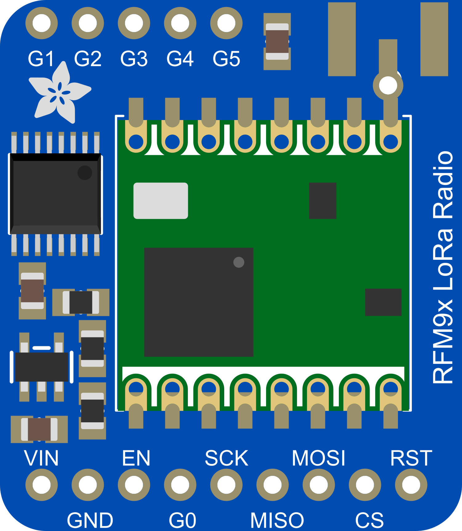
Pin Configuration and Descriptions
| Pin Number | Name | Description |
|---|---|---|
| 1 | GND | Ground connection |
| 2 | 3V3 | 3.3V power supply input |
| 3 | EN | Enable pin (active high) |
| 4 | G0 | GPIO0, used for interrupt signaling |
| 5 | RST | Reset pin (active low) |
| 6 | SCK | SPI Clock |
| 7 | MISO | SPI Master In Slave Out |
| 8 | MOSI | SPI Master Out Slave In |
| 9 | CS | SPI Chip Select |
| 10 | G1 | GPIO1, can be used for LoRa timing |
| 11 | G2 | GPIO2, general purpose I/O |
| 12 | G3 | GPIO3, general purpose I/O |
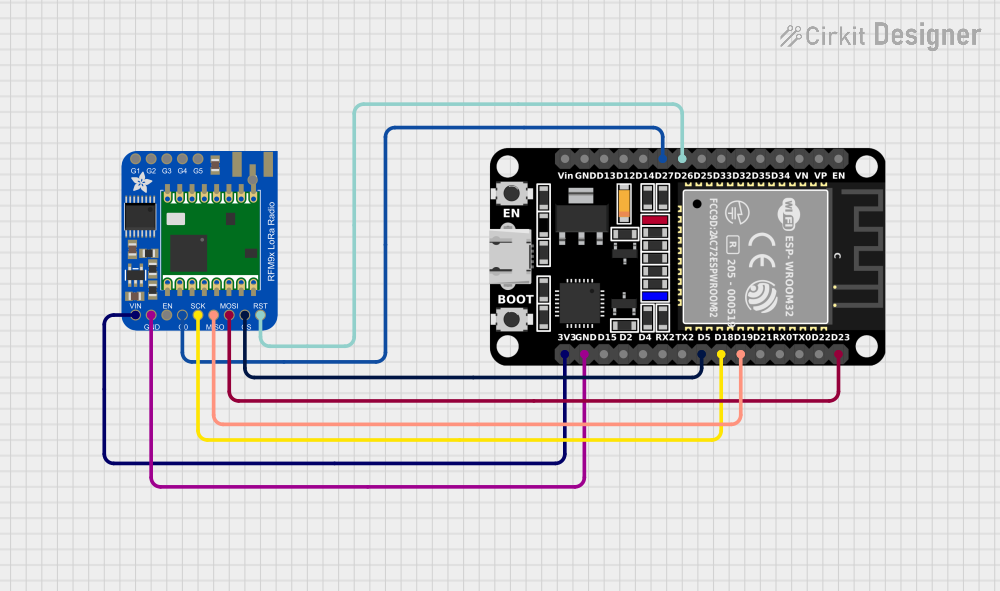
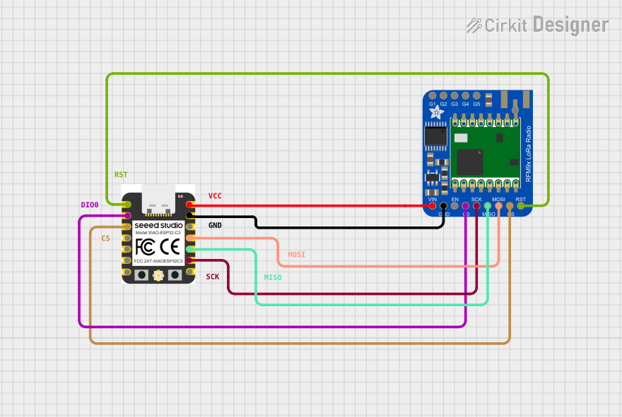
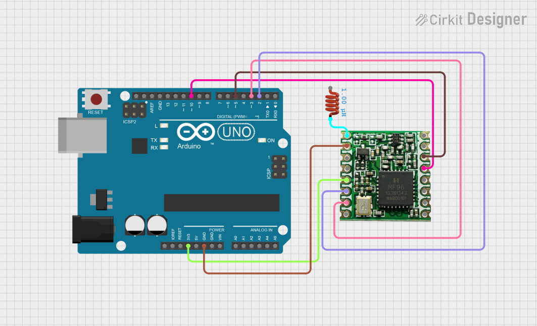
Usage Instructions
Integration with a Circuit
To use the Adafruit RFM9x LoRa Radio in a circuit:
- Connect the
3V3andGNDpins to a stable 3.3V power supply. - Interface the SPI pins (
SCK,MISO,MOSI,CS) with your microcontroller's SPI interface. - Connect the
ENpin to a digital output on your microcontroller if you wish to control the module's power state. - Attach an appropriate antenna to the antenna connector for your frequency band.
Best Practices
- Ensure that the power supply is clean and stable to avoid communication errors.
- Use a level shifter if you are interfacing with a 5V microcontroller.
- Place the module away from noise sources and metal objects to minimize interference.
- Always use an antenna that is tuned for the frequency band of your module.
Example Code for Arduino UNO
#include <SPI.h>
#include <RH_RF95.h>

// Singleton instance of the radio driver
RH_RF95 rf95;

void setup() {
  Serial.begin(9600);
  if (!rf95.init()) {
    Serial.println("LoRa radio init failed");
    while (1);
  }
  Serial.println("LoRa radio init OK!");
  if (!rf95.setFrequency(915.0)) {
    Serial.println("setFrequency failed");
    while (1);
  }
  rf95.setTxPower(13, false);
}

void loop() {
  Serial.println("Sending to rf95_server");
  // Send a message to rf95_server
  uint8_t data[] = "Hello World!";
  rf95.send(data, sizeof(data));

  rf95.waitPacketSent();
  // Now wait for a reply
  uint8_t buf[RH_RF95_MAX_MESSAGE_LEN];
  uint8_t len = sizeof(buf);

  if (rf95.waitAvailableTimeout(3000)) {
    // Should be a reply message for us now
    if (rf95.recv(buf, &len)) {
      Serial.print("Got reply: ");
      Serial.println((char*)buf);
    } else {
      Serial.println("Receive failed");
    }
  } else {
    Serial.println("No reply, is there a listener around?");
  }
  delay(4000);
}
Troubleshooting and FAQs
Common Issues
- No Communication: Ensure that the antenna is properly connected and the frequency settings match on both the transmitter and receiver.
- Short Range: Check for obstacles or interference sources. Make sure the antenna is appropriate for the frequency and is positioned correctly.
- Power Issues: Verify that the power supply is 3.3V and can provide sufficient current.
FAQs
Q: Can I use the RFM9x with a 5V microcontroller? A: Yes, but you will need to use a level shifter for the SPI lines to avoid damaging the module.
Q: How can I increase the range of the module? A: Use a high-gain antenna, reduce data rate, increase transmit power (within legal limits), and ensure line-of-sight where possible.
Q: What is the maximum data rate I can achieve? A: The maximum data rate is 300 kbps, but lower data rates can significantly increase the communication range.
Q: Is the module compatible with all LoRaWAN networks? A: The RFM9x module can be used with LoRaWAN networks, but you will need to implement the LoRaWAN protocol stack in your software.
For further assistance, consult the Adafruit RFM9x LoRa Radio datasheet and the manufacturer's support forums.