
How to Use CRD5114P Stepper Motor Driver: Examples, Pinouts, and Specs
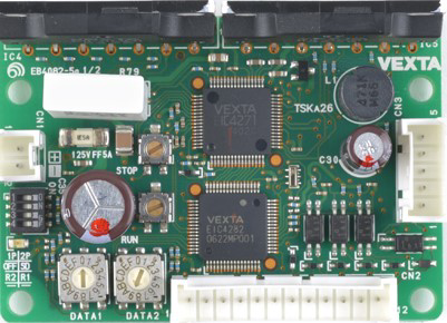
 Design with CRD5114P Stepper Motor Driver in Cirkit Designer
Introduction
The CRD5114P is a stepper motor driver manufactured by Oriental Motor. It is designed to control the movement of stepper motors with high precision and reliability. This driver supports microstepping, which allows for smoother motion and finer control over speed and position. The CRD5114P is ideal for applications requiring precise motor control, such as robotics, CNC machinery, 3D printers, and automated systems.
Explore Projects Built with CRD5114P Stepper Motor Driver
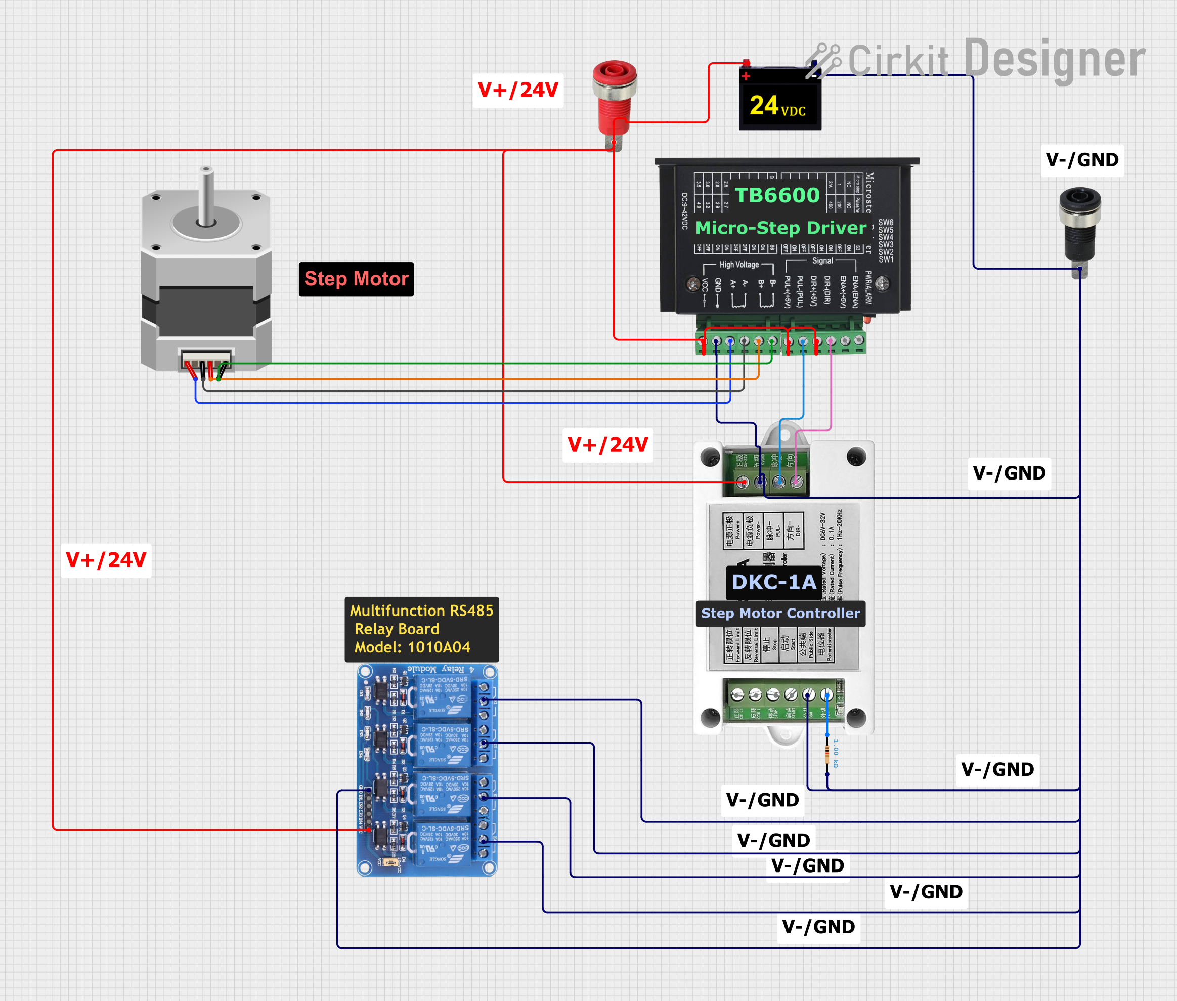 Open Project in Cirkit Designer
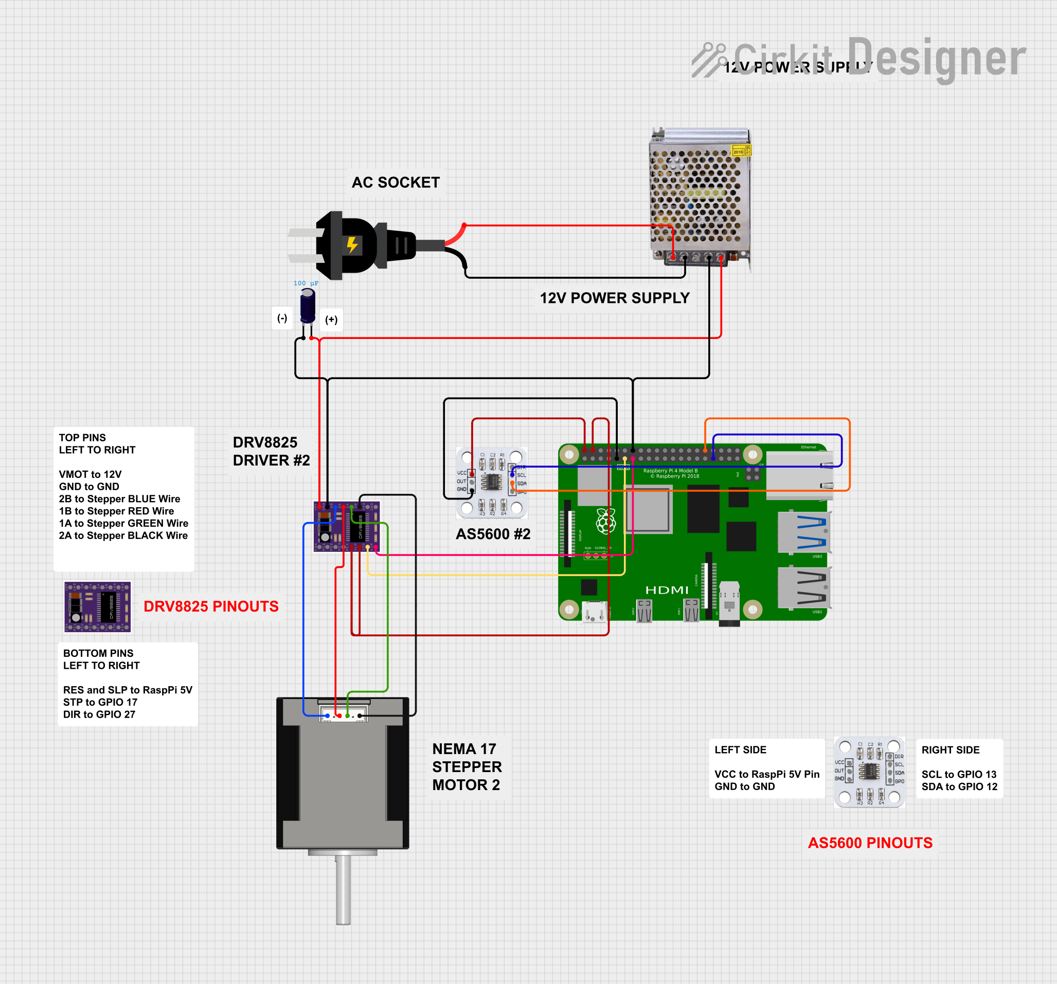 Open Project in Cirkit Designer
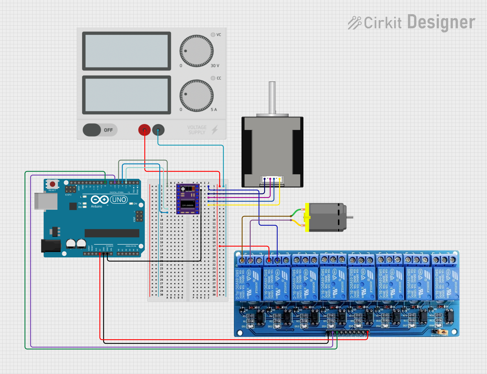 Open Project in Cirkit Designer
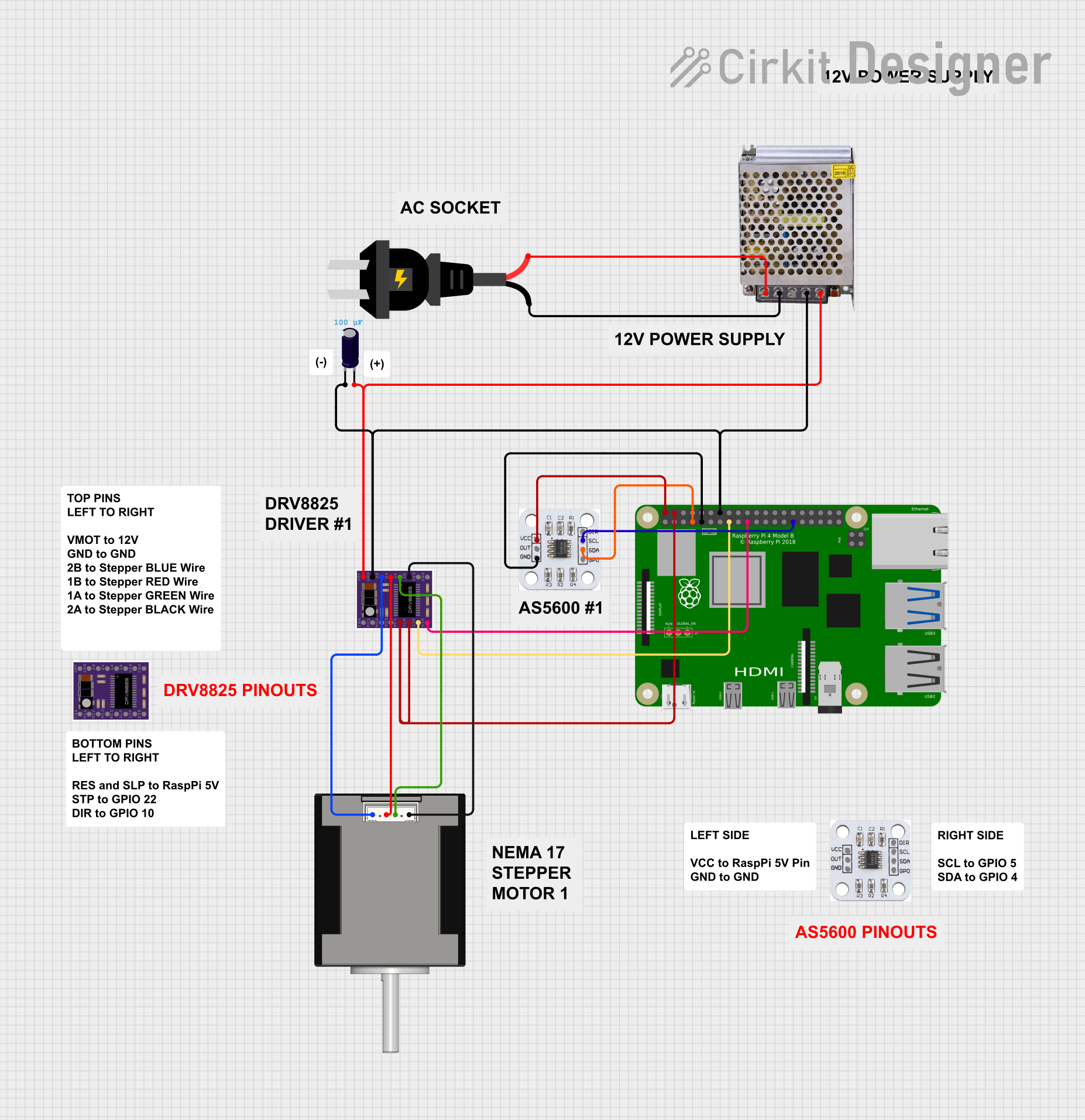 Open Project in Cirkit Designer
Explore Projects Built with CRD5114P Stepper Motor Driver
Open Project in Cirkit DesignerOpen Project in Cirkit DesignerOpen Project in Cirkit DesignerOpen Project in Cirkit DesignerCommon Applications:
- Robotics and automation
- CNC machinery
- 3D printing
- Conveyor systems
- Positioning systems in industrial equipment
Technical Specifications
The CRD5114P stepper motor driver is engineered to deliver optimal performance for stepper motors. Below are its key technical details:
Key Specifications:
| Parameter | Value |
|---|---|
| Input Voltage | 24–36 VDC |
| Output Current | 0.5–1.4 A/phase (adjustable) |
| Microstepping Resolution | Up to 1/16 step |
| Control Signal Input | Pulse and Direction |
| Operating Temperature | 0°C to 50°C |
| Dimensions | 90 mm x 60 mm x 30 mm |
| Weight | 200 g |
Pin Configuration and Descriptions:
The CRD5114P features a set of input and output terminals for connecting to the motor, power supply, and control signals. Below is the pin configuration:
Power and Motor Connections:
| Pin Name | Description |
|---|---|
| V+ | Positive terminal for power supply (24–36 VDC) |
| V- | Negative terminal for power supply (GND) |
| A+ | Motor winding A positive terminal |
| A- | Motor winding A negative terminal |
| B+ | Motor winding B positive terminal |
| B- | Motor winding B negative terminal |
Control Signal Inputs:
| Pin Name | Description |
|---|---|
| PUL+ | Positive terminal for pulse signal |
| PUL- | Negative terminal for pulse signal |
| DIR+ | Positive terminal for direction signal |
| DIR- | Negative terminal for direction signal |
| ENA+ | Positive terminal for enable signal |
| ENA- | Negative terminal for enable signal |
Usage Instructions
The CRD5114P is straightforward to use in a circuit. Follow the steps below to integrate it into your system:
Step 1: Power Supply Connection
- Connect the V+ and V- terminals to a DC power supply within the range of 24–36 VDC.
- Ensure the power supply can provide sufficient current for the motor and driver.
Step 2: Motor Connection
- Connect the stepper motor windings to the A+, A-, B+, and B- terminals.
- Verify the wiring sequence matches the motor's datasheet to avoid incorrect operation.
Step 3: Control Signal Connection
- Connect the PUL+, PUL-, DIR+, DIR-, ENA+, and ENA- terminals to your microcontroller or control system.
- Use optocouplers or resistors if necessary to match the voltage levels of the control signals.
Step 4: Adjusting Current and Microstepping
- Use the DIP switches on the driver to set the desired current limit and microstepping resolution.
- Refer to the CRD5114P datasheet for the DIP switch configuration table.
Step 5: Programming with Arduino UNO (Example Code)
The CRD5114P can be controlled using an Arduino UNO. Below is an example code snippet to control the stepper motor:
// Define control pins
const int pulsePin = 3;  // Pin connected to PUL+ (Pulse)
const int dirPin = 4;    // Pin connected to DIR+ (Direction)
const int enablePin = 5; // Pin connected to ENA+ (Enable)

void setup() {
  // Set pin modes
  pinMode(pulsePin, OUTPUT);
  pinMode(dirPin, OUTPUT);
  pinMode(enablePin, OUTPUT);

  // Enable the driver
  digitalWrite(enablePin, HIGH); // HIGH enables the driver
}

void loop() {
  // Set direction
  digitalWrite(dirPin, HIGH); // HIGH for clockwise, LOW for counterclockwise

  // Generate pulses to move the motor
  for (int i = 0; i < 200; i++) { // 200 steps for one revolution (1.8°/step)
    digitalWrite(pulsePin, HIGH);
    delayMicroseconds(500); // Adjust for speed control
    digitalWrite(pulsePin, LOW);
    delayMicroseconds(500);
  }

  delay(1000); // Wait for 1 second before reversing direction

  // Reverse direction
  digitalWrite(dirPin, LOW);

  // Generate pulses for reverse motion
  for (int i = 0; i < 200; i++) {
    digitalWrite(pulsePin, HIGH);
    delayMicroseconds(500);
    digitalWrite(pulsePin, LOW);
    delayMicroseconds(500);
  }

  delay(1000); // Wait for 1 second before repeating
}
Important Considerations:
- Ensure the power supply voltage and current ratings match the motor and driver requirements.
- Avoid disconnecting the motor while the driver is powered to prevent damage.
- Use proper heat dissipation methods if the driver operates at high currents for extended periods.
Troubleshooting and FAQs
Common Issues and Solutions:
Motor Not Moving:
- Verify all connections, especially the motor windings and control signals.
- Check the power supply voltage and current ratings.
- Ensure the enable signal (ENA+) is set to HIGH.
Motor Vibrates but Does Not Rotate:
- Check the wiring sequence of the motor windings (A+, A-, B+, B-).
- Ensure the microstepping settings are configured correctly.
Overheating Driver:
- Reduce the current limit using the DIP switches.
- Improve ventilation or add a heatsink to the driver.
Inconsistent Motor Movement:
- Verify the pulse signal timing and ensure it matches the motor's step rate.
- Check for noise or interference in the control signals.
FAQs:
Q: Can I use a 12 V power supply with the CRD5114P?
A: No, the CRD5114P requires a power supply within the range of 24–36 VDC.
Q: How do I set the microstepping resolution?
A: Use the DIP switches on the driver to configure the microstepping resolution. Refer to the datasheet for the specific settings.
Q: Is the CRD5114P compatible with NEMA 17 stepper motors?
A: Yes, as long as the motor's current and voltage ratings are within the driver's specifications.
Q: Can I control multiple drivers with one Arduino?
A: Yes, you can control multiple drivers by assigning separate pins for each driver's control signals.
This concludes the documentation for the CRD5114P Stepper Motor Driver. For further details, refer to the official datasheet provided by Oriental Motor.