How to Use Heltec Wireless Tracker v1.1: Examples, Pinouts, and Specs
Introduction
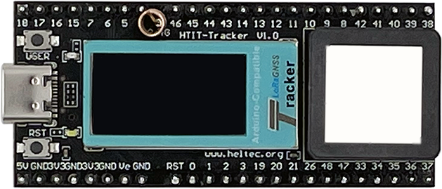
The Heltec Wireless Tracker v1.1 is a compact, low-power device designed for tracking and monitoring applications. It integrates GPS, Wi-Fi, and LoRa connectivity, making it an ideal solution for Internet of Things (IoT) projects. This versatile module is widely used in asset tracking, environmental monitoring, and remote data collection systems. Its small form factor and energy-efficient design make it suitable for battery-powered applications.
Explore Projects Built with Heltec Wireless Tracker v1.1
Explore Projects Built with Heltec Wireless Tracker v1.1
Common Applications and Use Cases
- Asset tracking (e.g., vehicles, equipment, or personal belongings)
- Environmental monitoring (e.g., weather stations, air quality sensors)
- Remote data collection in IoT networks
- Smart agriculture and livestock tracking
- Logistics and supply chain monitoring
Technical Specifications
The following table outlines the key technical details of the Heltec Wireless Tracker v1.1:
| Parameter | Specification |
|---|---|
| Manufacturer | Heltec |
| Part ID | Heltec Wireless Tracker v1.1 |
| Microcontroller | ESP32 (dual-core, 240 MHz, Wi-Fi, Bluetooth) |
| GPS Module | Built-in Ublox GPS module |
| LoRa Module | SX1276 (433/470/868/915 MHz, depending on region) |
| Flash Memory | 8 MB |
| Operating Voltage | 3.3V |
| Input Voltage Range | 3.7V to 4.2V (via LiPo battery) or 5V (via USB) |
| Power Consumption | ~10 mA (standby), ~120 mA (active, GPS + LoRa) |
| Antenna Interfaces | IPEX connectors for LoRa and GPS antennas |
| Dimensions | 41 mm x 25 mm x 7 mm |
| Operating Temperature | -40°C to 85°C |
Pin Configuration and Descriptions
The Heltec Wireless Tracker v1.1 features a compact pinout for easy integration into custom circuits. Below is the pin configuration:
| Pin Name | Description |
|---|---|
| 3V3 | 3.3V power output |
| GND | Ground |
| GPIO0 | General-purpose I/O, used for programming |
| GPIO16 | General-purpose I/O, LoRa DIO0 |
| GPIO17 | General-purpose I/O, LoRa DIO1 |
| TXD0 | UART0 Transmit |
| RXD0 | UART0 Receive |
| SDA | I2C Data Line |
| SCL | I2C Clock Line |
| BAT | Battery input (3.7V LiPo) |
| RST | Reset pin |
Usage Instructions
How to Use the Component in a Circuit
Powering the Device:
- Connect a 3.7V LiPo battery to the
BATpin or supply 5V via the USB port. - Ensure the battery is properly charged for optimal performance.
- Connect a 3.7V LiPo battery to the
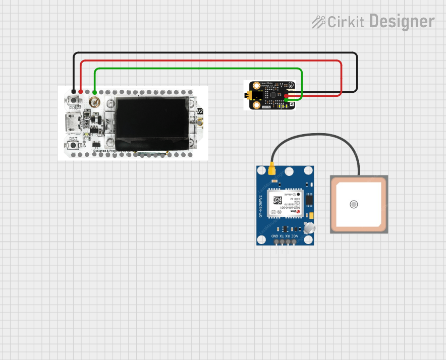
Connecting Antennas:
- Attach the LoRa and GPS antennas to their respective IPEX connectors.
- Ensure the antennas are securely connected to avoid signal loss.
Programming the Device:
- Use the USB port to connect the device to a computer.
- Install the necessary drivers for the ESP32 microcontroller.
- Use the Arduino IDE or PlatformIO to upload code. Select the board as "Heltec ESP32 LoRa" in the IDE.
Interfacing with Sensors:
- Use the I2C pins (
SDAandSCL) to connect external sensors. - Use GPIO pins for additional digital or analog inputs/outputs.
- Use the I2C pins (
LoRa Communication:
- Configure the LoRa module using the
LoRalibrary in Arduino IDE. - Set the frequency according to your region (e.g., 868 MHz for Europe, 915 MHz for the US).
- Configure the LoRa module using the
GPS Functionality:
- Use the
TinyGPS++library to parse GPS data. - Ensure the GPS antenna has a clear view of the sky for accurate positioning.
- Use the
Important Considerations and Best Practices
- Power Management: Use deep sleep mode to conserve battery life during idle periods.
- Antenna Placement: Position the antennas away from metal objects to minimize interference.
- Frequency Compliance: Ensure the LoRa frequency is compliant with local regulations.
- Firmware Updates: Regularly update the firmware to benefit from performance improvements and bug fixes.
Example Code for Arduino UNO
Below is an example code snippet to initialize the LoRa and GPS modules:
#include <LoRa.h>
#include <TinyGPS++.h>
#include <HardwareSerial.h>

// Define LoRa pins
#define LORA_SCK  5
#define LORA_MISO 19
#define LORA_MOSI 27
#define LORA_CS   18
#define LORA_RST  14
#define LORA_IRQ  26

// Initialize GPS
TinyGPSPlus gps;
HardwareSerial gpsSerial(1); // Use UART1 for GPS

void setup() {
  // Initialize Serial Monitor
  Serial.begin(115200);
  while (!Serial);

  // Initialize GPS
  gpsSerial.begin(9600, SERIAL_8N1, 16, 17); // RX=16, TX=17
  Serial.println("GPS Initialized");

  // Initialize LoRa
  LoRa.setPins(LORA_CS, LORA_RST, LORA_IRQ);
  if (!LoRa.begin(868E6)) { // Set frequency to 868 MHz
    Serial.println("LoRa initialization failed!");
    while (1);
  }
  Serial.println("LoRa Initialized");
}

void loop() {
  // Read GPS data
  while (gpsSerial.available() > 0) {
    gps.encode(gpsSerial.read());
    if (gps.location.isUpdated()) {
      Serial.print("Latitude: ");
      Serial.println(gps.location.lat(), 6);
      Serial.print("Longitude: ");
      Serial.println(gps.location.lng(), 6);
    }
  }

  // Send data via LoRa
  LoRa.beginPacket();
  LoRa.print("Hello from Heltec Wireless Tracker!");
  LoRa.endPacket();

  delay(5000); // Wait 5 seconds before sending the next packet
}
Troubleshooting and FAQs
Common Issues and Solutions
Device Not Powering On:
- Ensure the battery is charged or the USB cable is properly connected.
- Check for loose connections on the
BATorGNDpins.
LoRa Communication Fails:
- Verify that the LoRa frequency matches the regional settings.
- Ensure the LoRa antenna is securely connected.
- Check for interference from nearby devices.
GPS Not Acquiring Signal:
- Ensure the GPS antenna has a clear view of the sky.
- Wait for a few minutes for the GPS module to acquire a fix.
- Check the GPS connections and baud rate in the code.
Code Upload Fails:
- Ensure the correct board and port are selected in the Arduino IDE.
- Press and hold the
RSTbutton while uploading the code.
FAQs
Q: Can I use this device without a battery?
A: Yes, you can power it via the USB port, but a battery is recommended for portability.Q: What is the maximum range of the LoRa module?
A: The range depends on environmental conditions but can reach up to 10 km in open areas.Q: Can I use this device with other microcontrollers?
A: Yes, you can interface it with other microcontrollers via UART, I2C, or GPIO pins.