How to Use gForceJoint UART 111: Examples, Pinouts, and Specs

gForceJoint UART 111 Documentation
1. Introduction
The gForceJoint UART 111 is a communication interface module manufactured by Oymotion. It utilizes the UART (Universal Asynchronous Receiver-Transmitter) protocol to facilitate serial communication between microcontrollers and embedded systems. This module is designed to transmit and receive data efficiently, making it an essential component in various applications.
Common Applications and Use Cases
- Microcontroller Communication: Facilitates data exchange between microcontrollers.
- Embedded Systems: Used in embedded systems for reliable serial communication.
- Robotics: Enables communication between different robotic components.
- IoT Devices: Integrates with IoT devices for data transmission.
- Data Logging: Collects and transmits data to a central system for logging and analysis.
2. Technical Specifications
Key Technical Details
| Parameter | Value |
|---|---|
| Operating Voltage | 3.3V - 5V |
| Current Consumption | 10mA |
| Baud Rate | 9600, 19200, 38400, 57600, 115200 bps |
| Communication Protocol | UART |
| Operating Temperature | -40°C to 85°C |
| Dimensions | 25mm x 15mm x 5mm |
Pin Configuration and Descriptions
| Pin Number | Pin Name | Description |
|---|---|---|
| 1 | VCC | Power Supply (3.3V - 5V) |
| 2 | GND | Ground |
| 3 | TXD | Transmit Data |
| 4 | RXD | Receive Data |
| 5 | RTS | Request to Send (optional) |
| 6 | CTS | Clear to Send (optional) |
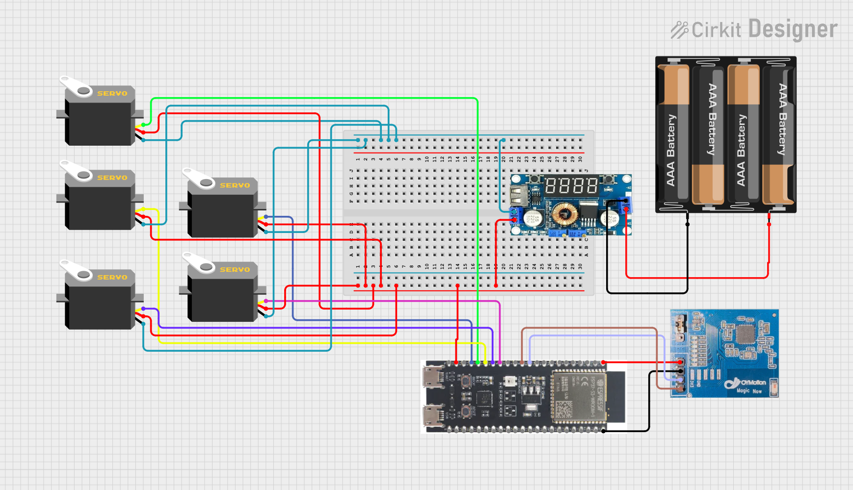
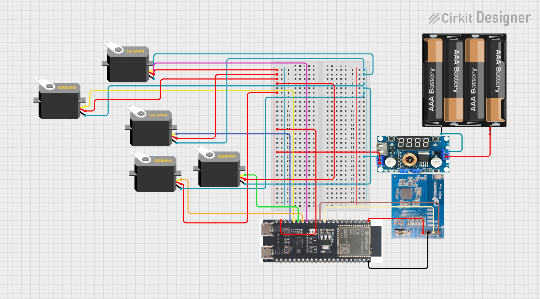
3. Usage Instructions
How to Use the Component in a Circuit
- Power Supply: Connect the VCC pin to a 3.3V or 5V power supply and the GND pin to the ground.
- Data Transmission: Connect the TXD pin to the RXD pin of the microcontroller and the RXD pin to the TXD pin of the microcontroller.
- Optional Flow Control: If using hardware flow control, connect the RTS and CTS pins accordingly.
Important Considerations and Best Practices
- Voltage Levels: Ensure that the voltage levels of the gForceJoint UART 111 and the microcontroller are compatible.
- Baud Rate: Set the baud rate of the module and the microcontroller to the same value for proper communication.
- Noise Reduction: Use decoupling capacitors near the power supply pins to reduce noise.
- Proper Grounding: Ensure a common ground between the module and the microcontroller to avoid communication issues.
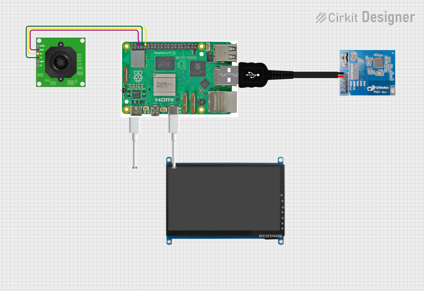
Example Circuit Diagram
Microcontroller          gForceJoint UART 111
     VCC  -------------------->  VCC
     GND  -------------------->  GND
     TXD  -------------------->  RXD
     RXD  -------------------->  TXD
Example Code for Arduino UNO
// Example code to communicate with gForceJoint UART 111 using Arduino UNO

void setup() {
  Serial.begin(9600); // Initialize serial communication at 9600 baud rate
}

void loop() {
  if (Serial.available()) {
    char receivedData = Serial.read(); // Read data from gForceJoint UART 111
    Serial.print("Received: ");
    Serial.println(receivedData); // Print received data to Serial Monitor
  }

  // Send data to gForceJoint UART 111
  Serial.print("Hello gForceJoint UART 111");
  delay(1000); // Wait for 1 second before sending the next message
}
4. Troubleshooting and FAQs
Common Issues Users Might Face
No Data Transmission:
- Solution: Check the connections, ensure the TXD and RXD pins are correctly connected.
- Tip: Verify that the baud rate settings match between the module and the microcontroller.
Garbage Data:
- Solution: Ensure proper grounding and check for noise in the power supply.
- Tip: Use shielded cables for long-distance communication.
Module Not Powering On:
- Solution: Verify the power supply voltage and current ratings.
- Tip: Check for loose connections or damaged wires.
FAQs
Q1: Can I use the gForceJoint UART 111 with a 3.3V microcontroller?
- A1: Yes, the module supports both 3.3V and 5V power supplies.
Q2: What is the maximum baud rate supported by the gForceJoint UART 111?
- A2: The maximum baud rate supported is 115200 bps.
Q3: Do I need to use the RTS and CTS pins?
- A3: The RTS and CTS pins are optional and used for hardware flow control. If not needed, they can be left unconnected.
Q4: How can I reduce noise in the communication?
- A4: Use decoupling capacitors near the power supply pins and ensure proper grounding.
Q5: Can I connect multiple gForceJoint UART 111 modules to a single microcontroller?
- A5: Yes, but you will need to manage the UART communication channels and ensure proper addressing.
This documentation provides a comprehensive guide to using the gForceJoint UART 111 module. By following the instructions and best practices, users can achieve reliable and efficient serial communication in their projects.
Explore Projects Built with gForceJoint UART 111

Explore Projects Built with gForceJoint UART 111