Cirkit Designer Logo
Cirkit Designer
Your all-in-one circuit design IDE
Home / 
Component Documentation

How to Use ttgo lora32: Examples, Pinouts, and Specs

Image of ttgo lora32
Cirkit Designer LogoDesign with ttgo lora32 in Cirkit Designer

Introduction

The TTGO LoRa32 is a versatile development board that integrates an ESP32 microcontroller with a LoRa transceiver. This combination allows for long-range wireless communication, making it an ideal choice for Internet of Things (IoT) projects. The board is known for its low power consumption and extensive connectivity options, which include Wi-Fi, Bluetooth, and LoRa. Common applications include remote sensing, environmental monitoring, and smart agriculture.

Explore Projects Built with ttgo lora32

Use Cirkit Designer to design, explore, and prototype these projects online. Some projects support real-time simulation. Click "Open Project" to start designing instantly!
ESP32C3 and LoRa-Enabled Environmental Sensing Node
Image of temperature_KA: A project utilizing ttgo lora32 in a practical application
This circuit features an ESP32C3 Supermini microcontroller connected to a LORA_RA02 module and a DHT11 temperature and humidity sensor. The ESP32C3 handles communication with the LORA module via SPI (using GPIO05, GPIO06, GPIO10, and GPIO04 for MISO, MOSI, NSS, and SCK respectively) and GPIO01 and GPIO02 for additional control signals. The DHT11 sensor is interfaced through GPIO03 for data reading, and all components share a common power supply through the 3.3V and GND pins.
Cirkit Designer LogoOpen Project in Cirkit Designer
LoRa-Enabled Wind Direction Monitoring System with TTGO LoRa32
Image of Proyek Angin: A project utilizing ttgo lora32 in a practical application
This circuit measures wind direction using a Wind Vane and a WindDirectionSensor, and transmits the data via a TTGO LoRa32 microcontroller. The Wind Vane and WindDirectionSensor are powered by the TTGO LoRa32, which also reads the sensor data and sends it wirelessly.
Cirkit Designer LogoOpen Project in Cirkit Designer
Cellular-Enabled IoT Device with Real-Time Clock and Power Management
Image of LRCM PHASE 2 BASIC: A project utilizing ttgo lora32 in a practical application
This circuit features a LilyGo-SIM7000G module for cellular communication and GPS functionality, interfaced with an RTC DS3231 for real-time clock capabilities. It includes voltage sensing through two voltage sensor modules, and uses an 8-channel opto-coupler for isolating different parts of the circuit. Power management is handled by a buck converter connected to a DC power source and batteries, with a fuse for protection and a rocker switch for on/off control. Additionally, there's an LED for indication purposes.
Cirkit Designer LogoOpen Project in Cirkit Designer
WiFi LoRa Environmental Monitoring System with INMP441 Mic and Multiple Sensors
Image of ba_sensing: A project utilizing ttgo lora32 in a practical application
This circuit is a solar-powered environmental monitoring system that uses a WiFi LoRa 32V3 microcontroller to collect data from various sensors, including a microphone, UV light sensor, air quality sensor, and temperature/humidity/pressure sensor. The collected data is processed and transmitted via LoRa communication, making it suitable for remote environmental data logging and monitoring applications.
Cirkit Designer LogoOpen Project in Cirkit Designer

Explore Projects Built with ttgo lora32

Use Cirkit Designer to design, explore, and prototype these projects online. Some projects support real-time simulation. Click "Open Project" to start designing instantly!
Image of temperature_KA: A project utilizing ttgo lora32 in a practical application
ESP32C3 and LoRa-Enabled Environmental Sensing Node
This circuit features an ESP32C3 Supermini microcontroller connected to a LORA_RA02 module and a DHT11 temperature and humidity sensor. The ESP32C3 handles communication with the LORA module via SPI (using GPIO05, GPIO06, GPIO10, and GPIO04 for MISO, MOSI, NSS, and SCK respectively) and GPIO01 and GPIO02 for additional control signals. The DHT11 sensor is interfaced through GPIO03 for data reading, and all components share a common power supply through the 3.3V and GND pins.
Cirkit Designer LogoOpen Project in Cirkit Designer
Image of Proyek Angin: A project utilizing ttgo lora32 in a practical application
LoRa-Enabled Wind Direction Monitoring System with TTGO LoRa32
This circuit measures wind direction using a Wind Vane and a WindDirectionSensor, and transmits the data via a TTGO LoRa32 microcontroller. The Wind Vane and WindDirectionSensor are powered by the TTGO LoRa32, which also reads the sensor data and sends it wirelessly.
Cirkit Designer LogoOpen Project in Cirkit Designer
Image of LRCM PHASE 2 BASIC: A project utilizing ttgo lora32 in a practical application
Cellular-Enabled IoT Device with Real-Time Clock and Power Management
This circuit features a LilyGo-SIM7000G module for cellular communication and GPS functionality, interfaced with an RTC DS3231 for real-time clock capabilities. It includes voltage sensing through two voltage sensor modules, and uses an 8-channel opto-coupler for isolating different parts of the circuit. Power management is handled by a buck converter connected to a DC power source and batteries, with a fuse for protection and a rocker switch for on/off control. Additionally, there's an LED for indication purposes.
Cirkit Designer LogoOpen Project in Cirkit Designer
Image of ba_sensing: A project utilizing ttgo lora32 in a practical application
WiFi LoRa Environmental Monitoring System with INMP441 Mic and Multiple Sensors
This circuit is a solar-powered environmental monitoring system that uses a WiFi LoRa 32V3 microcontroller to collect data from various sensors, including a microphone, UV light sensor, air quality sensor, and temperature/humidity/pressure sensor. The collected data is processed and transmitted via LoRa communication, making it suitable for remote environmental data logging and monitoring applications.
Cirkit Designer LogoOpen Project in Cirkit Designer

Technical Specifications

Key Technical Details

Parameter Specification
Microcontroller ESP32
LoRa Transceiver SX1276
Operating Voltage 3.3V
Input Voltage 5V (via USB)
Flash Memory 4MB
SRAM 520KB
Wi-Fi 802.11 b/g/n
Bluetooth v4.2 BR/EDR and BLE
Frequency Range 868/915 MHz (LoRa)
Communication Range Up to 10 km (line of sight)
Power Consumption Low power modes available

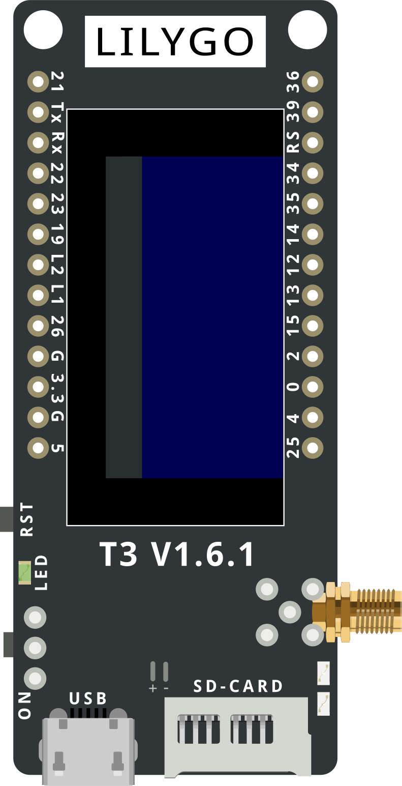
Pin Configuration and Descriptions

Pin Number Pin Name Description
1 GND Ground
2 3V3 3.3V Power Output
3 EN Enable Pin
4 23 GPIO23
5 22 GPIO22
6 21 GPIO21
7 19 GPIO19
8 18 GPIO18
9 17 GPIO17
10 16 GPIO16
11 15 GPIO15
12 14 GPIO14
13 13 GPIO13
14 12 GPIO12
15 11 GPIO11
16 10 GPIO10
17 9 GPIO9
18 8 GPIO8
19 7 GPIO7
20 6 GPIO6
21 5 GPIO5
22 4 GPIO4
23 3 GPIO3
24 2 GPIO2
25 1 GPIO1
26 0 GPIO0

Usage Instructions

How to Use the Component in a Circuit

  1. Powering the Board:

    • Connect the TTGO LoRa32 to your computer using a USB cable. This will provide the necessary 5V input voltage.
    • Alternatively, you can power the board using a 3.7V LiPo battery connected to the battery connector.
  2. Programming the Board:

    • Install the Arduino IDE and add the ESP32 board support by following the instructions on the ESP32 Arduino GitHub page.
    • Select "TTGO LoRa32" from the board manager.
    • Write your code and upload it to the board.
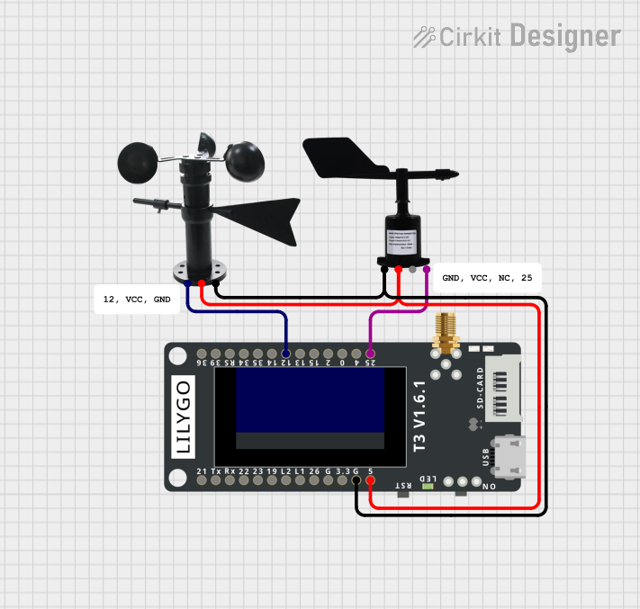
  3. Connecting Sensors and Actuators:

    • Use the GPIO pins to connect various sensors and actuators. Refer to the pin configuration table for pin assignments.

Important Considerations and Best Practices

  • Antenna Connection: Ensure that the LoRa antenna is properly connected to the board to achieve optimal communication range.
  • Power Management: Utilize the low power modes of the ESP32 to extend battery life in IoT applications.
  • Pin Usage: Be mindful of the pin assignments, especially when using peripherals like I2C, SPI, or UART.

Example Code for Arduino UNO

#include <SPI.h>
#include <LoRa.h>

#define SS 18
#define RST 14
#define DI0 26

void setup() {
  Serial.begin(9600);
  while (!Serial);

  // Setup LoRa transceiver module
  LoRa.setPins(SS, RST, DI0);
  
  if (!LoRa.begin(915E6)) {
    Serial.println("Starting LoRa failed!");
    while (1);
  }
  Serial.println("LoRa Initializing OK!");
}

void loop() {
  Serial.print("Sending packet: ");
  Serial.println("Hello World!");

  // Send packet
  LoRa.beginPacket();
  LoRa.print("Hello World!");
  LoRa.endPacket();

  delay(10000); // Wait for 10 seconds before sending next packet
}

Troubleshooting and FAQs

Common Issues Users Might Face

  1. LoRa Initialization Failed:

    • Solution: Ensure that the LoRa antenna is connected and that the correct pins are defined in the code.
  2. Board Not Recognized by Computer:

    • Solution: Check the USB cable and port. Ensure that the correct drivers are installed.
  3. Upload Errors:

    • Solution: Verify that the correct board and port are selected in the Arduino IDE.

Solutions and Tips for Troubleshooting

  • Check Connections: Ensure all connections are secure and correct.
  • Update Firmware: Make sure the ESP32 firmware is up to date.
  • Consult Documentation: Refer to the official TTGO LoRa32 documentation for more detailed information.

By following this documentation, users should be able to effectively utilize the TTGO LoRa32 development board in their IoT projects, leveraging its powerful features for long-range wireless communication.