How to Use SMPS 5V 60A: Examples, Pinouts, and Specs
Introduction
The SMPS 5V 60A is a high-efficiency Switch Mode Power Supply designed to convert electrical power into a stable 5V DC output with a maximum current capacity of 60A. This component is ideal for applications requiring a reliable and robust power source, such as powering LED strips, industrial control systems, high-current microcontroller projects, and other electronic devices.
Explore Projects Built with SMPS 5V 60A


Explore Projects Built with SMPS 5V 60A
Common Applications and Use Cases
- Powering high-current LED lighting systems
- Supplying power to industrial automation equipment
- Driving motors and actuators in robotics
- Providing power to large-scale microcontroller or single-board computer projects
- Charging battery packs or powering DC loads
Technical Specifications
The following table outlines the key technical details of the SMPS 5V 60A:
| Parameter | Value |
|---|---|
| Input Voltage Range | 100-240V AC (50/60Hz) |
| Output Voltage | 5V DC |
| Maximum Output Current | 60A |
| Maximum Output Power | 300W |
| Efficiency | ≥ 85% |
| Ripple and Noise | ≤ 120mV |
| Operating Temperature | -10°C to +50°C |
| Cooling Method | Forced air cooling (fan) |
| Protection Features | Overload, overvoltage, and short-circuit protection |
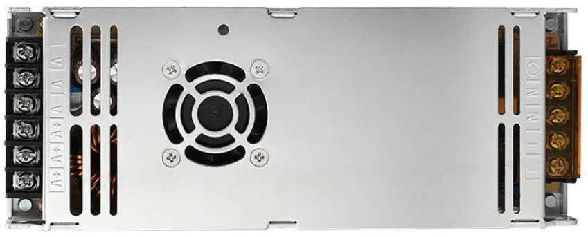
Pin Configuration and Descriptions
The SMPS 5V 60A typically has the following input and output terminals:
| Pin/Terminal | Label | Description |
|---|---|---|
| 1 | L | Live AC input (100-240V AC) |
| 2 | N | Neutral AC input |
| 3 | GND | Earth/ground connection |
| 4 | V+ | Positive DC output (5V) |
| 5 | V+ | Positive DC output (5V) |
| 6 | V- | Negative DC output (ground) |
| 7 | V- | Negative DC output (ground) |
| 8 | ADJ | Voltage adjustment potentiometer (±10% adjustment) |
Usage Instructions
How to Use the SMPS 5V 60A in a Circuit
Input Connection:
- Connect the AC input terminals (
LandN) to a 100-240V AC power source. - Ensure the ground terminal (
GND) is properly connected to the earth for safety.
- Connect the AC input terminals (
Output Connection:
- Use the
V+terminals to connect to the positive side of your load. - Use the
V-terminals to connect to the negative side (ground) of your load. - For high-current applications, distribute the load evenly across multiple
V+andV-terminals.
- Use the
Voltage Adjustment:
- If necessary, use the
ADJpotentiometer to fine-tune the output voltage within ±10% of 5V.
- If necessary, use the
Cooling and Ventilation:
- Ensure adequate airflow around the SMPS to prevent overheating.
- Do not block the cooling fan or ventilation holes.
Load Considerations:
- Do not exceed the maximum output current of 60A.
- For inductive loads (e.g., motors), consider adding a flyback diode to protect the SMPS.
Important Considerations and Best Practices
- Always verify the input voltage range before connecting the SMPS to the power source.
- Use appropriately rated wires and connectors to handle the high current output.
- Avoid operating the SMPS at full load for extended periods to prolong its lifespan.
- Ensure proper grounding to minimize electrical noise and improve safety.
- If using the SMPS with sensitive electronics, consider adding additional filtering capacitors to reduce ripple and noise.
Example: Connecting to an Arduino UNO
The SMPS 5V 60A can be used to power an Arduino UNO and other peripherals. Below is an example of how to connect it:
- Connect the
V+terminal of the SMPS to the Arduino's5Vpin. - Connect the
V-terminal of the SMPS to the Arduino'sGNDpin. - Ensure the SMPS is properly grounded and ventilated.
Here is a simple Arduino code example to blink an LED while powered by the SMPS:
// This code blinks an LED connected to pin 13 of the Arduino UNO.
// Ensure the Arduino is powered by the SMPS 5V 60A.

void setup() {
  pinMode(13, OUTPUT); // Set pin 13 as an output pin
}

void loop() {
  digitalWrite(13, HIGH); // Turn the LED on
  delay(1000);            // Wait for 1 second
  digitalWrite(13, LOW);  // Turn the LED off
  delay(1000);            // Wait for 1 second
}
Troubleshooting and FAQs
Common Issues and Solutions
No Output Voltage:
- Cause: Input power is not connected or is outside the specified range.
- Solution: Verify the AC input voltage and connections.
Overheating:
- Cause: Insufficient ventilation or operating at full load for extended periods.
- Solution: Ensure proper airflow and reduce the load if necessary.
Output Voltage Fluctuations:
- Cause: Load exceeds the maximum current rating or poor connections.
- Solution: Check the load and ensure secure connections to the terminals.
Fan Not Working:
- Cause: Fan failure or blocked ventilation.
- Solution: Inspect the fan and clear any obstructions. Replace the fan if necessary.
High Ripple or Noise:
- Cause: Insufficient filtering for sensitive electronics.
- Solution: Add external capacitors or filters to the output.
FAQs
Q1: Can I use the SMPS 5V 60A to charge batteries?
A1: Yes, but ensure the battery charging circuit includes proper current and voltage regulation to prevent overcharging.
Q2: Is the SMPS suitable for outdoor use?
A2: No, the SMPS is not weatherproof. Use it in a dry, indoor environment or within a weatherproof enclosure.
Q3: Can I adjust the output voltage beyond 5V?
A3: The ADJ potentiometer allows for a ±10% adjustment, so the output voltage can be fine-tuned between approximately 4.5V and 5.5V.
Q4: What happens if the load exceeds 60A?
A4: The SMPS includes overload protection and will shut down to prevent damage. Reduce the load and restart the SMPS.
Q5: How do I know if the SMPS is working correctly?
A5: Use a multimeter to measure the output voltage and ensure it is stable at 5V. Check the fan operation and ensure the load is functioning as expected.