How to Use qt-py: Examples, Pinouts, and Specs
Introduction
The QT Py is a small, lightweight microcontroller board designed for easy integration with various sensors and components. It features a compact form factor, making it ideal for projects where space is limited. The QT Py is compatible with both CircuitPython and Arduino, offering flexibility for developers of all skill levels. Despite its small size, it is packed with powerful features, making it suitable for a wide range of applications.
Explore Projects Built with qt-py


Explore Projects Built with qt-py
Common Applications and Use Cases
- Wearable electronics
- IoT (Internet of Things) devices
- Prototyping and rapid development
- Robotics and automation
- Educational projects and learning platforms
Technical Specifications
The QT Py is based on the SAMD21 or RP2040 microcontroller (depending on the variant) and offers the following key specifications:
| Specification | Details |
|---|---|
| Microcontroller | SAMD21 Cortex-M0+ (48 MHz) or RP2040 dual-core Cortex-M0+ (133 MHz) |
| Flash Memory | 256 KB (SAMD21) or 2 MB (RP2040) |
| RAM | 32 KB (SAMD21) or 264 KB (RP2040) |
| Operating Voltage | 3.3V |
| Input Voltage | 5V via USB-C |
| GPIO Pins | 11 (including I2C, SPI, UART, and analog inputs) |
| USB Interface | USB-C connector for power, programming, and data |
| Dimensions | 22.9 mm x 17.8 mm |
| Programming Support | CircuitPython, Arduino IDE, and MicroPython |
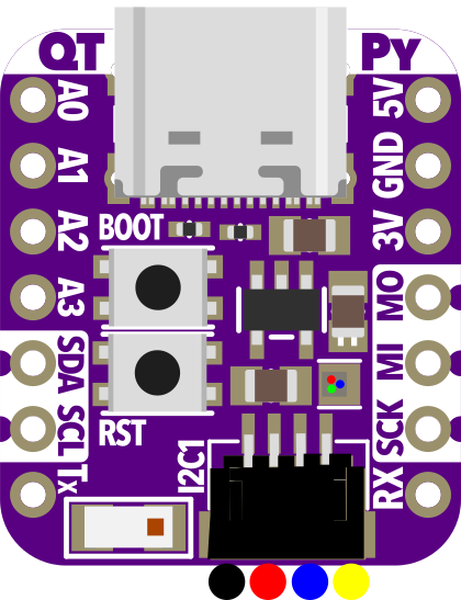
Pin Configuration and Descriptions
The QT Py features a total of 14 pins, including power, ground, and GPIO. Below is the pinout description:
| Pin | Label | Function |
|---|---|---|
| 1 | 3V | 3.3V power output |
| 2 | GND | Ground connection |
| 3 | A0 | Analog input or digital GPIO (ADC capable) |
| 4 | A1 | Analog input or digital GPIO (ADC capable) |
| 5 | SDA | I2C data line |
| 6 | SCL | I2C clock line |
| 7 | TX | UART transmit line |
| 8 | RX | UART receive line |
| 9 | SCK | SPI clock line |
| 10 | MISO | SPI master-in-slave-out line |
| 11 | MOSI | SPI master-out-slave-in line |
| 12 | D4 | Digital GPIO |
| 13 | D5 | Digital GPIO |
| 14 | USB-C | USB-C connector for power, programming, and data |
Usage Instructions
How to Use the QT Py in a Circuit
Powering the QT Py:
- Connect the QT Py to a computer or USB power source using a USB-C cable.
- The board operates at 3.3V internally, but it can accept 5V input via USB.
Connecting Components:
- Use the GPIO pins to connect sensors, actuators, or other peripherals.
- For I2C devices, connect to the
SDAandSCLpins. - For SPI devices, use the
SCK,MISO, andMOSIpins.
Programming the QT Py:
- Install CircuitPython or Arduino IDE on your computer.
- For CircuitPython, copy the
.uf2firmware file to the QT Py when it appears as a USB drive. - For Arduino, select the appropriate board and port in the IDE, then upload your sketch.
Important Considerations and Best Practices
- Voltage Levels: Ensure all connected components operate at 3.3V logic levels to avoid damaging the board.
- Pin Limitations: Avoid exceeding the current limits of the GPIO pins (typically 7-10 mA per pin).
- Heat Management: While the QT Py is efficient, avoid placing it in enclosed spaces without ventilation during high-load operations.
- Firmware Updates: Regularly update the firmware to access new features and bug fixes.
Example: Blinking an LED with Arduino
Here is an example of how to blink an LED connected to pin D4 using the Arduino IDE:
// Define the pin for the LED
const int ledPin = 4; // Pin D4 on the QT Py

void setup() {
  // Set the LED pin as an output
  pinMode(ledPin, OUTPUT);
}

void loop() {
  // Turn the LED on
  digitalWrite(ledPin, HIGH);
  delay(1000); // Wait for 1 second

  // Turn the LED off
  digitalWrite(ledPin, LOW);
  delay(1000); // Wait for 1 second
}
Example: Reading a Sensor with CircuitPython
Here is an example of reading an analog sensor connected to pin A0 using CircuitPython:
import board
import analogio
import time
Initialize the analog input on pin A0
sensor = analogio.AnalogIn(board.A0)
def get_voltage(pin): # Convert the raw analog value to a voltage return (pin.value * 3.3) / 65536
while True: # Read and print the sensor voltage voltage = get_voltage(sensor) print("Sensor Voltage:", voltage) time.sleep(1) # Wait for 1 second
Troubleshooting and FAQs
Common Issues and Solutions
QT Py Not Recognized by Computer:
- Ensure the USB-C cable is data-capable (not just a charging cable).
- Try a different USB port or cable.
- Double-tap the reset button to enter bootloader mode.
CircuitPython Drive Not Appearing:
- Verify that CircuitPython firmware is installed.
- If the board is in bootloader mode, copy the
.uf2file to the drive that appears.
Components Not Responding:
- Check wiring and ensure proper connections to the GPIO pins.
- Verify that the components are compatible with 3.3V logic levels.
Overheating:
- Disconnect the board and check for short circuits.
- Ensure the board is not drawing excessive current from connected components.
FAQs
Q: Can I power the QT Py with a battery?
A: Yes, you can use a 3.7V LiPo battery with a suitable regulator to provide 3.3V to the board.
Q: Is the QT Py compatible with MicroPython?
A: Yes, the RP2040 variant supports MicroPython, while the SAMD21 variant is optimized for CircuitPython.
Q: How do I reset the QT Py?
A: Press the reset button once to restart the board. Double-tap the reset button to enter bootloader mode.
Q: Can I use the QT Py for audio processing?
A: While the QT Py is not specifically designed for audio processing, the RP2040 variant can handle basic audio tasks with external components.
By following this documentation, you can effectively integrate the QT Py into your projects and troubleshoot common issues.