Cirkit Designer Logo
Cirkit Designer
Your all-in-one circuit design IDE
Home / 
Component Documentation

How to Use ams1117 5v: Examples, Pinouts, and Specs
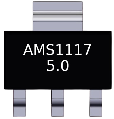

Image of ams1117 5v
Cirkit Designer LogoDesign with ams1117 5v in Cirkit Designer

Introduction

The AMS1117 5V is a low dropout (LDO) voltage regulator designed to provide a stable 5V output from a higher input voltage. It is widely used in power supply circuits to ensure consistent voltage levels for sensitive electronic components. With its compact size and reliable performance, the AMS1117 5V is a popular choice for powering microcontrollers, sensors, and other low-power devices.

Explore Projects Built with ams1117 5v
Use Cirkit Designer to design, explore, and prototype these projects online. Some projects support real-time simulation. Click "Open Project" to start designing instantly!
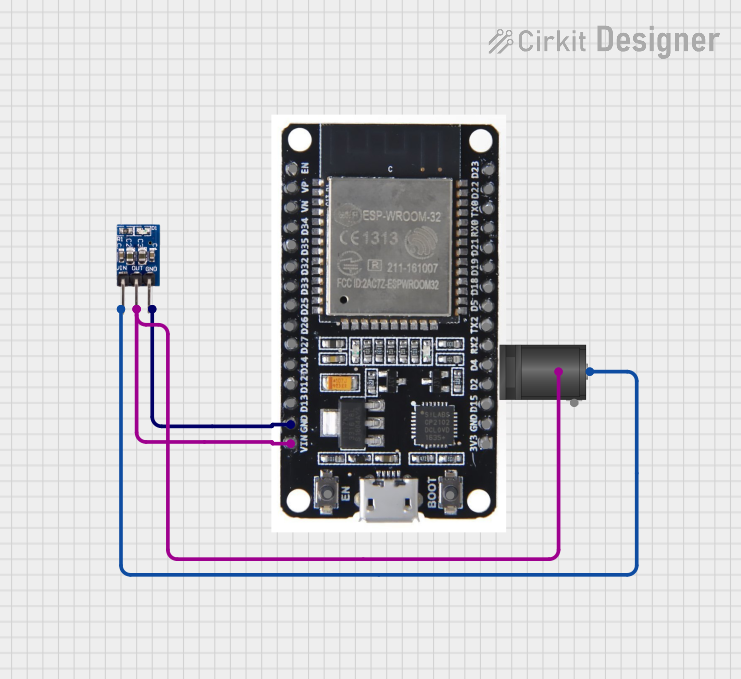
ESP32-Powered Wi-Fi Enabled Microcontroller Circuit with AMS1117 Voltage Regulation
Image of Power regualator: A project utilizing ams1117 5v in a practical application
This circuit features an ESP32 microcontroller powered by a 3.3V AMS1117 voltage regulator. The power is supplied through a 2.1mm DC barrel jack, which provides the input voltage to the AMS1117, and the regulated 3.3V output is connected to the ESP32's VIN pin. The ground connections are shared among the ESP32 and the voltage regulator.
Cirkit Designer LogoOpen Project in Cirkit Designer
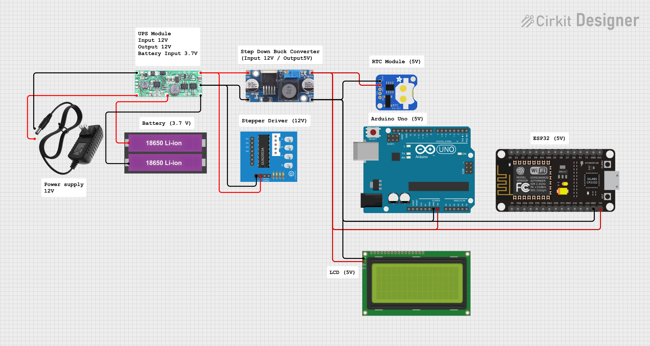
Battery-Powered Arduino UNO and ESP-8266 Smart Controller with LCD and RTC
Image of Ogie Diagram: A project utilizing ams1117 5v in a practical application
This circuit is a power management and control system that uses a 12V power supply and a 18650 Li-ion battery pack to provide a stable 5V output through a step-down buck converter. It includes an Arduino UNO, an ESP-8266 controller, a DS1307 RTC module, and a 20x4 I2C LCD display for monitoring and control purposes. The ULN2003A breakout board is used for driving higher current loads.
Cirkit Designer LogoOpen Project in Cirkit Designer
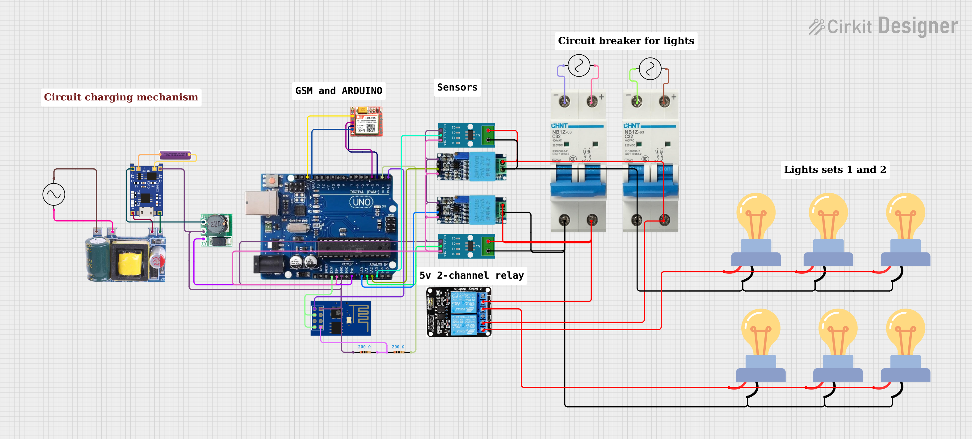
Arduino and GSM-Based Power Monitoring and Wi-Fi Controlled Lighting System
Image of light monitoring system: A project utilizing ams1117 5v in a practical application
This circuit is designed to monitor voltage and current using ACS712 current sensors and voltage sensors, calculate power, and control lighting via relay modules. It features an Arduino Uno R3 for processing sensor data and executing control logic, which includes sending alerts via a GSM module (sim 800l) if power falls below a threshold and connecting to WiFi using an ESP8266 module. The circuit also includes a battery with a charging module (TP4056), a step-up boost converter, and multiple AC power supplies with circuit breakers for safety.
Cirkit Designer LogoOpen Project in Cirkit Designer
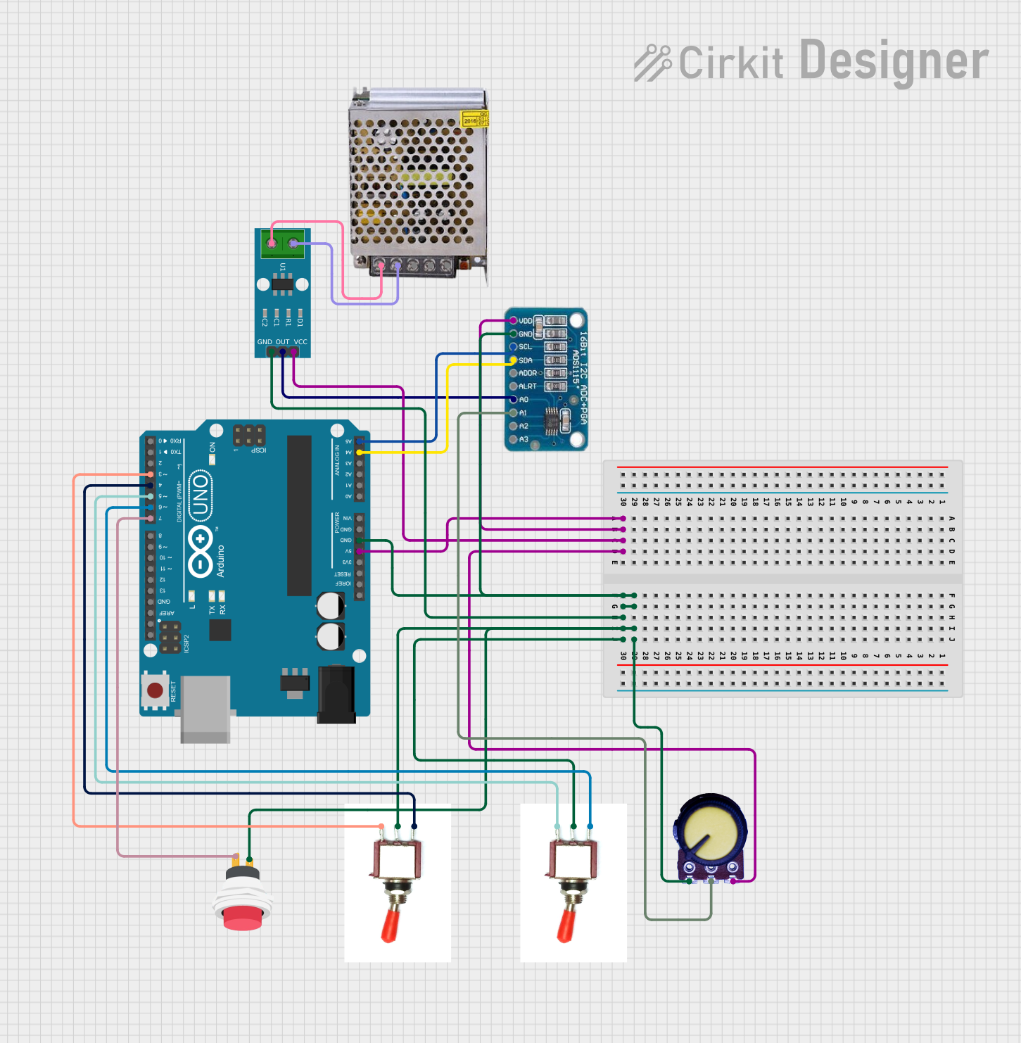
Arduino UNO with ADS1115 ADC and ACS712 Current Sensor Monitoring System
Image of ADC: A project utilizing ams1117 5v in a practical application
This circuit features an Arduino UNO microcontroller interfaced with an ADS1115 ADC for precise analog-to-digital conversion, an ACS712 current sensor for current measurement, and a potentiometer for adjustable input. It includes toggle switches and a push button for user input, with the Arduino programmed to read and process sensor data, switch states, and potentiometer values, outputting the information via serial communication for monitoring or further processing.
Cirkit Designer LogoOpen Project in Cirkit Designer

Explore Projects Built with ams1117 5v

Use Cirkit Designer to design, explore, and prototype these projects online. Some projects support real-time simulation. Click "Open Project" to start designing instantly!
Image of Power regualator: A project utilizing ams1117 5v in a practical application
ESP32-Powered Wi-Fi Enabled Microcontroller Circuit with AMS1117 Voltage Regulation
This circuit features an ESP32 microcontroller powered by a 3.3V AMS1117 voltage regulator. The power is supplied through a 2.1mm DC barrel jack, which provides the input voltage to the AMS1117, and the regulated 3.3V output is connected to the ESP32's VIN pin. The ground connections are shared among the ESP32 and the voltage regulator.
Cirkit Designer LogoOpen Project in Cirkit Designer
Image of Ogie Diagram: A project utilizing ams1117 5v in a practical application
Battery-Powered Arduino UNO and ESP-8266 Smart Controller with LCD and RTC
This circuit is a power management and control system that uses a 12V power supply and a 18650 Li-ion battery pack to provide a stable 5V output through a step-down buck converter. It includes an Arduino UNO, an ESP-8266 controller, a DS1307 RTC module, and a 20x4 I2C LCD display for monitoring and control purposes. The ULN2003A breakout board is used for driving higher current loads.
Cirkit Designer LogoOpen Project in Cirkit Designer
Image of light monitoring system: A project utilizing ams1117 5v in a practical application
Arduino and GSM-Based Power Monitoring and Wi-Fi Controlled Lighting System
This circuit is designed to monitor voltage and current using ACS712 current sensors and voltage sensors, calculate power, and control lighting via relay modules. It features an Arduino Uno R3 for processing sensor data and executing control logic, which includes sending alerts via a GSM module (sim 800l) if power falls below a threshold and connecting to WiFi using an ESP8266 module. The circuit also includes a battery with a charging module (TP4056), a step-up boost converter, and multiple AC power supplies with circuit breakers for safety.
Cirkit Designer LogoOpen Project in Cirkit Designer
Image of ADC: A project utilizing ams1117 5v in a practical application
Arduino UNO with ADS1115 ADC and ACS712 Current Sensor Monitoring System
This circuit features an Arduino UNO microcontroller interfaced with an ADS1115 ADC for precise analog-to-digital conversion, an ACS712 current sensor for current measurement, and a potentiometer for adjustable input. It includes toggle switches and a push button for user input, with the Arduino programmed to read and process sensor data, switch states, and potentiometer values, outputting the information via serial communication for monitoring or further processing.
Cirkit Designer LogoOpen Project in Cirkit Designer

Common Applications and Use Cases

  • Powering microcontrollers such as Arduino, ESP8266, and Raspberry Pi peripherals
  • Voltage regulation for sensors and modules in embedded systems
  • Battery-powered devices requiring a stable 5V output
  • DIY electronics projects and prototyping

Technical Specifications

The AMS1117 5V voltage regulator has the following key specifications:

Parameter Value
Output Voltage 5V ± 1%
Input Voltage Range 6.5V to 12V
Maximum Output Current 1A
Dropout Voltage 1.1V (at 1A load)
Quiescent Current 5mA (typical)
Operating Temperature -40°C to +125°C
Package Type SOT-223, TO-252

Pin Configuration and Descriptions

The AMS1117 5V typically comes in a 3-pin SOT-223 package. The pinout is as follows:

Pin Number Pin Name Description
1 GND Ground pin (connect to circuit ground)
2 VOUT Regulated 5V output
3 VIN Input voltage (6.5V to 12V recommended)

Usage Instructions

How to Use the AMS1117 5V in a Circuit

  1. Input Voltage: Connect a DC voltage source (6.5V to 12V) to the VIN pin. Ensure the input voltage is at least 1.1V higher than the desired 5V output to maintain proper regulation.
  2. Output Voltage: Connect the VOUT pin to the load or circuit requiring a 5V supply.
  3. Ground Connection: Connect the GND pin to the ground of the circuit.
  4. Capacitors: Add decoupling capacitors for stable operation:
    • Place a 10µF capacitor between VIN and GND.
    • Place a 10µF capacitor between VOUT and GND.

Important Considerations and Best Practices

  • Heat Dissipation: The AMS1117 5V can generate heat under high current loads. Use a heatsink or ensure proper ventilation if the current exceeds 500mA.
  • Input Voltage Range: Avoid exceeding the maximum input voltage of 12V to prevent damage to the regulator.
  • Capacitor Placement: Place the capacitors as close as possible to the regulator pins to minimize noise and ensure stability.
  • Current Limitation: Do not exceed the maximum output current of 1A to avoid overheating or damage.

Example: Using AMS1117 5V with Arduino UNO

The AMS1117 5V can be used to power an Arduino UNO from a 9V battery. Below is an example circuit and Arduino code:

Circuit Connections

  • Connect the 9V battery's positive terminal to the VIN pin of the AMS1117.
  • Connect the 9V battery's negative terminal to the GND pin of the AMS1117.
  • Connect the VOUT pin of the AMS1117 to the Arduino UNO's 5V pin.
  • Connect the GND pin of the AMS1117 to the Arduino UNO's GND pin.

Arduino Code Example

// Example code to blink an LED connected to pin 13 of Arduino UNO
// Ensure the AMS1117 5V is providing a stable 5V to the Arduino

void setup() {
  pinMode(13, OUTPUT); // Set pin 13 as an output pin
}

void loop() {
  digitalWrite(13, HIGH); // Turn the LED on
  delay(1000);            // Wait for 1 second
  digitalWrite(13, LOW);  // Turn the LED off
  delay(1000);            // Wait for 1 second
}

Troubleshooting and FAQs

Common Issues and Solutions

  1. No Output Voltage

    • Cause: Insufficient input voltage.
    • Solution: Ensure the input voltage is at least 6.5V.
  2. Overheating

    • Cause: Excessive current draw or high input voltage.
    • Solution: Reduce the load current or use a heatsink for better heat dissipation.
  3. Unstable Output Voltage

    • Cause: Missing or improperly placed capacitors.
    • Solution: Add 10µF capacitors close to the VIN and VOUT pins.
  4. Output Voltage Too Low

    • Cause: High dropout voltage due to low input voltage.
    • Solution: Increase the input voltage to at least 6.5V.

FAQs

Q1: Can the AMS1117 5V regulate a 5V input to 5V output?
A1: No, the AMS1117 requires an input voltage at least 1.1V higher than the output voltage. For a 5V output, the input voltage must be at least 6.5V.

Q2: What is the maximum current the AMS1117 5V can supply?
A2: The AMS1117 5V can supply up to 1A of current, but proper heat dissipation is required for high current loads.

Q3: Can I use the AMS1117 5V with a 12V input?
A3: Yes, the AMS1117 5V can handle a 12V input, but ensure adequate cooling to prevent overheating.

Q4: Do I need external components to use the AMS1117 5V?
A4: Yes, decoupling capacitors (10µF) are required on both the input and output for stable operation.