How to Use Zener Diode 4.7V: Examples, Pinouts, and Specs
Introduction
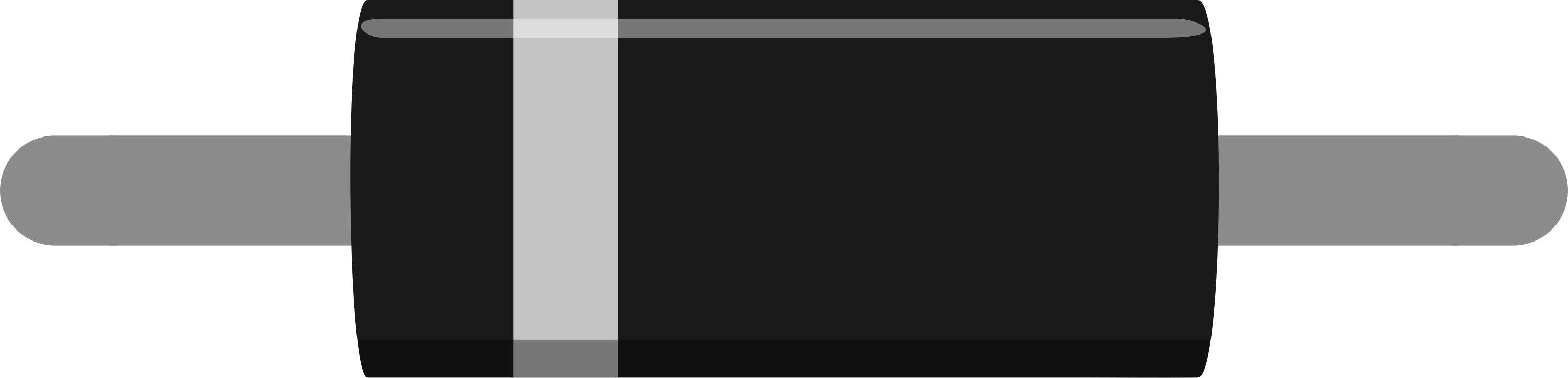
The Zener Diode 4.7V is a specialized semiconductor device designed to maintain a constant voltage of 4.7 volts across its terminals when reverse-biased. This makes it an essential component for voltage regulation and protection in electronic circuits. Unlike standard diodes, which block current in reverse bias, the Zener diode allows current to flow in reverse once the breakdown voltage (4.7V in this case) is reached, ensuring stable voltage levels.
Explore Projects Built with Zener Diode 4.7V


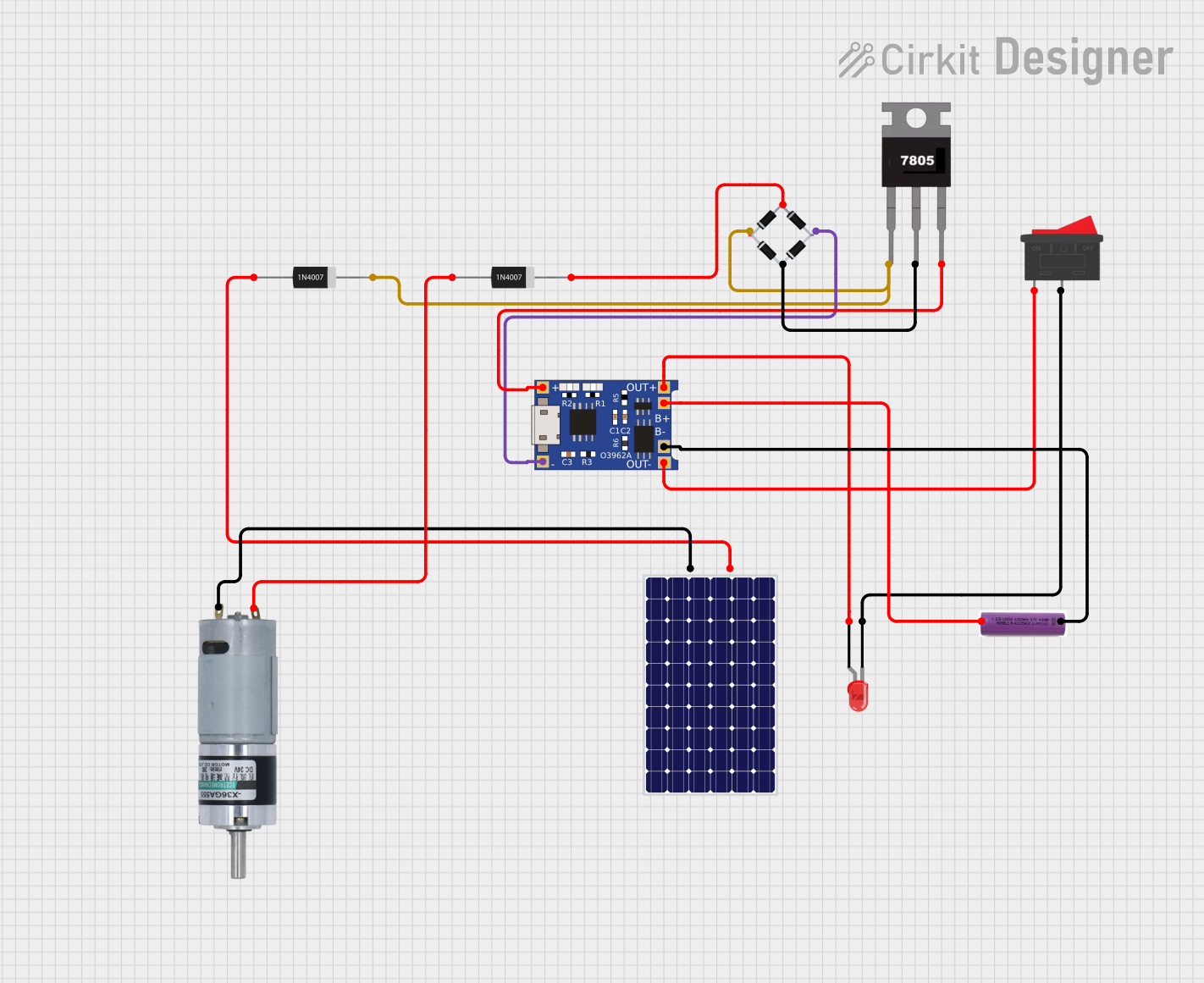

Explore Projects Built with Zener Diode 4.7V
Common Applications and Use Cases
- Voltage regulation in power supplies
- Overvoltage protection for sensitive components
- Reference voltage generation in analog and digital circuits
- Clipping and clamping circuits in signal processing
Technical Specifications
The following table outlines the key technical details of the Zener Diode 4.7V:
| Parameter | Value |
|---|---|
| Nominal Zener Voltage | 4.7V |
| Maximum Power Dissipation | 500mW (typical) |
| Zener Current Range | 5mA to 50mA |
| Maximum Reverse Current | 5µA (at 1V reverse bias) |
| Operating Temperature | -55°C to +150°C |
| Package Type | DO-35 (commonly used) |
Pin Configuration and Descriptions
The Zener diode has two terminals:
| Pin | Name | Description |
|---|---|---|
| 1 | Cathode | Connected to the negative terminal in reverse bias. |
| 2 | Anode | Connected to the positive terminal in reverse bias. |
Usage Instructions
How to Use the Zener Diode 4.7V in a Circuit
- Voltage Regulation: Connect the Zener diode in reverse bias across the load. Ensure the cathode is connected to the positive voltage source and the anode to the ground.
- Current Limiting Resistor: Always use a series resistor to limit the current through the Zener diode. This prevents overheating and ensures the diode operates within its specified range.
- Calculate the resistor value using Ohm's Law:
( R = \frac{V_{in} - V_Z}{I_Z} )
Where ( V_{in} ) is the input voltage, ( V_Z ) is the Zener voltage (4.7V), and ( I_Z ) is the desired Zener current.
- Calculate the resistor value using Ohm's Law:
- Power Dissipation: Ensure the power dissipation across the diode does not exceed its maximum rating (500mW).
- Power dissipation can be calculated as:
( P = V_Z \times I_Z ).
- Power dissipation can be calculated as:
Example Circuit with Arduino UNO
The Zener diode can be used to protect the analog input pin of an Arduino UNO from overvoltage. Below is an example:
Circuit Description
- The Zener diode is connected in reverse bias across the analog input pin and ground.
- A resistor is placed in series with the input voltage to limit the current.
Code Example
// Arduino code to read an analog voltage protected by a Zener diode
const int analogPin = A0; // Analog pin connected to the Zener-protected input

void setup() {
  Serial.begin(9600); // Initialize serial communication at 9600 baud
}

void loop() {
  int sensorValue = analogRead(analogPin); // Read the analog input
  float voltage = sensorValue * (5.0 / 1023.0); // Convert to voltage
  Serial.print("Voltage: ");
  Serial.print(voltage);
  Serial.println(" V");
  delay(1000); // Wait for 1 second before the next reading
}
Important Considerations and Best Practices
- Current Limiting: Always use a resistor to limit the current through the Zener diode.
- Power Rating: Ensure the diode's power dissipation does not exceed its maximum rating.
- Polarity: Double-check the polarity of the Zener diode during installation. Reverse polarity can damage the diode or the circuit.
- Operating Range: Use the diode within its specified voltage and current range for optimal performance.
Troubleshooting and FAQs
Common Issues and Solutions
Zener Diode Overheating
- Cause: Excessive current through the diode.
- Solution: Use a higher-value series resistor to limit the current.
Voltage Not Regulated at 4.7V
- Cause: Insufficient input voltage or incorrect resistor value.
- Solution: Ensure the input voltage is at least 1-2V higher than the Zener voltage. Recalculate the resistor value.
No Voltage Across the Diode
- Cause: Incorrect polarity or damaged diode.
- Solution: Verify the diode's orientation and replace it if necessary.
Arduino Analog Pin Reading Incorrect Values
- Cause: Noise or insufficient current limiting.
- Solution: Add a capacitor (e.g., 0.1µF) across the Zener diode for noise filtering and verify the resistor value.
FAQs
Q1: Can I use the Zener Diode 4.7V without a series resistor?
A1: No, a series resistor is essential to limit the current through the diode and prevent damage.
Q2: What happens if the input voltage is lower than 4.7V?
A2: The Zener diode will not conduct in reverse bias, and the output voltage will be equal to the input voltage.
Q3: Can I use this Zener diode for AC voltage regulation?
A3: Zener diodes are typically used for DC voltage regulation. For AC applications, additional components like rectifiers are required.
Q4: How do I calculate the power dissipation of the Zener diode?
A4: Multiply the Zener voltage (4.7V) by the current flowing through the diode to calculate power dissipation. Ensure it does not exceed the maximum rating (500mW).