Cirkit Designer Logo
Cirkit Designer
Your all-in-one circuit design IDE
Home / 
Component Documentation

How to Use SparkFun USB MicroB Plug Breakout: Examples, Pinouts, and Specs

Image of SparkFun USB MicroB Plug Breakout
Cirkit Designer LogoDesign with SparkFun USB MicroB Plug Breakout in Cirkit Designer

Introduction

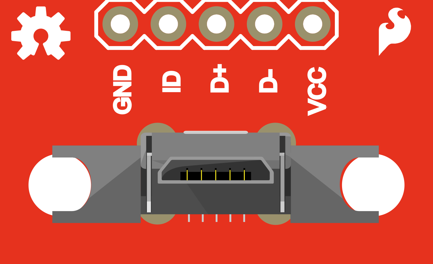
The SparkFun USB MicroB Plug Breakout is a versatile and compact breakout board designed to simplify the use of a USB MicroB connector in your projects. This breakout board is ideal for hobbyists and engineers who need to incorporate USB connectivity into their designs. Common applications include creating custom USB cables, interfacing with USB devices, and prototyping USB-powered electronics.

Explore Projects Built with SparkFun USB MicroB Plug Breakout

Use Cirkit Designer to design, explore, and prototype these projects online. Some projects support real-time simulation. Click "Open Project" to start designing instantly!
ESP32 CAM Wi-Fi Enabled Camera Module with USB Power
Image of abc: A project utilizing SparkFun USB MicroB Plug Breakout in a practical application
This circuit consists of an ESP32 CAM module powered by a Micro USB breakout board. The USB breakout board supplies 5V and ground to the ESP32 CAM, enabling it to function and perform tasks such as image capture and processing.
Cirkit Designer LogoOpen Project in Cirkit Designer
ESP32 CAM-Based Impact Detection System with Serial Communication and LED Indicator
Image of esp32 cam: A project utilizing SparkFun USB MicroB Plug Breakout in a practical application
This circuit features an ESP32 CAM module interfaced with a SparkFun USB UART Breakout for serial communication, allowing the ESP32 to communicate with a computer or other USB host. A BC547 transistor is used to control an LED, with the base driven by one of the ESP32's GPIO pins through a resistor, and multiple piezo sensors are connected to the transistor's emitter, likely for sensing vibrations or impacts. The 5V Adapter provides power to the ESP32 and the LED, while the ground connections are shared among the components.
Cirkit Designer LogoOpen Project in Cirkit Designer
USB-Powered LED Indicator with NPN Transistor Control
Image of UAS: A project utilizing SparkFun USB MicroB Plug Breakout in a practical application
This circuit is a simple LED driver powered via a Micro USB breakout board. It uses an NPN transistor to control the illumination of a red and a green LED, with current-limiting resistors in place to protect the LEDs.
Cirkit Designer LogoOpen Project in Cirkit Designer
Bluetooth-Controlled Robotic Vehicle with Ultrasonic Obstacle Detection and Motion Sensing
Image of 아두이노 드론: A project utilizing SparkFun USB MicroB Plug Breakout in a practical application
This circuit features a SparkFun Pro Micro microcontroller interfaced with an L298N DC motor driver to control two DC motors, an HC-SR04 ultrasonic sensor for distance measurement, a Bluetooth module HM-10 for wireless communication, and an MPU-6050 for motion tracking. The Pro Micro is responsible for processing sensor data and managing motor speeds and directions via the motor driver. Power is supplied by a 5V battery connected to the Pro Micro and a separate battery case providing 12V to the motor driver.
Cirkit Designer LogoOpen Project in Cirkit Designer

Explore Projects Built with SparkFun USB MicroB Plug Breakout

Use Cirkit Designer to design, explore, and prototype these projects online. Some projects support real-time simulation. Click "Open Project" to start designing instantly!
Image of abc: A project utilizing SparkFun USB MicroB Plug Breakout in a practical application
ESP32 CAM Wi-Fi Enabled Camera Module with USB Power
This circuit consists of an ESP32 CAM module powered by a Micro USB breakout board. The USB breakout board supplies 5V and ground to the ESP32 CAM, enabling it to function and perform tasks such as image capture and processing.
Cirkit Designer LogoOpen Project in Cirkit Designer
Image of esp32 cam: A project utilizing SparkFun USB MicroB Plug Breakout in a practical application
ESP32 CAM-Based Impact Detection System with Serial Communication and LED Indicator
This circuit features an ESP32 CAM module interfaced with a SparkFun USB UART Breakout for serial communication, allowing the ESP32 to communicate with a computer or other USB host. A BC547 transistor is used to control an LED, with the base driven by one of the ESP32's GPIO pins through a resistor, and multiple piezo sensors are connected to the transistor's emitter, likely for sensing vibrations or impacts. The 5V Adapter provides power to the ESP32 and the LED, while the ground connections are shared among the components.
Cirkit Designer LogoOpen Project in Cirkit Designer
Image of UAS: A project utilizing SparkFun USB MicroB Plug Breakout in a practical application
USB-Powered LED Indicator with NPN Transistor Control
This circuit is a simple LED driver powered via a Micro USB breakout board. It uses an NPN transistor to control the illumination of a red and a green LED, with current-limiting resistors in place to protect the LEDs.
Cirkit Designer LogoOpen Project in Cirkit Designer
Image of 아두이노 드론: A project utilizing SparkFun USB MicroB Plug Breakout in a practical application
Bluetooth-Controlled Robotic Vehicle with Ultrasonic Obstacle Detection and Motion Sensing
This circuit features a SparkFun Pro Micro microcontroller interfaced with an L298N DC motor driver to control two DC motors, an HC-SR04 ultrasonic sensor for distance measurement, a Bluetooth module HM-10 for wireless communication, and an MPU-6050 for motion tracking. The Pro Micro is responsible for processing sensor data and managing motor speeds and directions via the motor driver. Power is supplied by a 5V battery connected to the Pro Micro and a separate battery case providing 12V to the motor driver.
Cirkit Designer LogoOpen Project in Cirkit Designer

Technical Specifications

Key Technical Details

  • Connector Type: USB Micro-B
  • USB Standard: USB 2.0
  • Operating Voltage: 5V (typical USB power line)
  • Maximum Current: 1.8A (subject to PCB trace width)

Pin Configuration and Descriptions

Pin Number Name Description
1 VBUS +5V power from USB
2 D- USB Data minus
3 D+ USB Data plus
4 ID Identification pin, typically not connected
5 GND Ground connection

Usage Instructions

How to Use the Component in a Circuit

  1. Power Connections: Connect the VBUS pin to the +5V power line in your circuit and the GND pin to the common ground.

  2. Data Connections: Connect the D+ and D- pins to your microcontroller or USB interface chip according to the datasheet of the device you are interfacing with.

  3. Mounting: Secure the breakout board to your project using the mounting holes provided.

Important Considerations and Best Practices

  • ESD Precautions: USB connectors are susceptible to electrostatic discharge. Handle the breakout board with proper ESD precautions.
  • Cable Quality: Use high-quality USB cables to ensure reliable data transfer.
  • Power Limitations: Do not exceed the maximum current rating of 1.8A.
  • Signal Integrity: Keep USB data lines as short as possible to maintain signal integrity.
  • Pull-up Resistors: Depending on your USB device, you may need to add pull-up resistors to the data lines.

Troubleshooting and FAQs

Common Issues

  • Device Not Recognized: Ensure that all connections are secure and that the correct drivers are installed for your USB device.
  • Intermittent Connection: Check for any loose connections or damaged cables. Also, inspect the breakout board for any signs of damage.

Solutions and Tips for Troubleshooting

  • Connection Issues: Double-check solder joints on the breakout board for cold solder or bridges.
  • Power Problems: Verify that the VBUS line is supplying a stable 5V power source.
  • Data Transfer Errors: Ensure that the D+ and D- lines are not too long and are routed away from sources of electromagnetic interference.

FAQs

  • Q: Can I use this breakout board for USB 3.0 devices?

    • A: No, this breakout board is designed for USB 2.0 connections only.
  • Q: How do I add this breakout board to my custom PCB design?

    • A: You can solder the breakout board directly to your PCB or use header pins for a removable connection.
  • Q: Is it possible to power a device through this breakout board?

    • A: Yes, as long as the power requirements do not exceed the 5V and 1.8A specifications.

Example Code for Arduino UNO

The following example demonstrates how to set up a simple serial communication through the USB MicroB Plug Breakout connected to an Arduino UNO.

// This example assumes the USB MicroB Plug Breakout is connected to a USB-to-Serial
// converter chip that interfaces with the Arduino UNO.

void setup() {
  // Begin serial communication at a baud rate of 9600.
  Serial.begin(9600);
}

void loop() {
  // Check if data is available to read.
  if (Serial.available() > 0) {
    // Read the incoming byte.
    char incomingByte = Serial.read();
    
    // Echo the byte back out through the serial port.
    Serial.write(incomingByte);
  }
}

Note: This code is for demonstration purposes and assumes that the USB MicroB Plug Breakout is part of a larger circuit capable of USB communication. The Arduino UNO itself has a built-in USB interface, and this example is to illustrate potential usage with compatible hardware.

Remember to consult the datasheet of the USB-to-Serial converter chip you are using for specific wiring and initialization instructions.