How to Use DC SURGE PROTECTION DEVICE: Examples, Pinouts, and Specs
Introduction
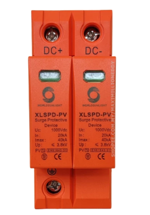
The DC Surge Protection Device (DC SPD), manufactured by DC SPD, is a critical component designed to safeguard electrical circuits from voltage spikes. By diverting excess voltage away from sensitive components, it ensures the longevity and reliability of electronic systems. This device is particularly useful in DC power systems, renewable energy setups (e.g., solar panels), and industrial applications where voltage surges are common.
Explore Projects Built with DC SURGE PROTECTION DEVICE


Explore Projects Built with DC SURGE PROTECTION DEVICE
Common Applications and Use Cases
- Protection of DC power systems in solar energy installations
- Safeguarding industrial equipment from transient voltage spikes
- Use in battery storage systems to prevent damage from overvoltage
- Protection of sensitive electronic devices in telecommunications and data centers
Technical Specifications
The following table outlines the key technical details of the DC SPD:
| Parameter | Value |
|---|---|
| Manufacturer | DC SPD |
| Part ID | DCSPD |
| Nominal Operating Voltage | 12V DC, 24V DC, 48V DC, 1000V DC |
| Maximum Discharge Current | 20 kA |
| Voltage Protection Level | ≤ 2.5 kV |
| Response Time | < 25 ns |
| Operating Temperature | -40°C to +85°C |
| Enclosure Material | Flame-retardant thermoplastic |
| Mounting Type | DIN Rail |
| Compliance Standards | IEC 61643-11, UL 1449 |
Pin Configuration and Descriptions
The DC SPD typically has a simple terminal configuration for easy integration into DC circuits. Below is the pin description:
| Pin/Terminal | Description |
|---|---|
| L+ | Positive DC input terminal |
| L- | Negative DC input terminal |
| PE | Protective Earth (ground connection) |
Usage Instructions
How to Use the DC SPD in a Circuit
- Identify the Voltage Rating: Ensure the DC SPD is rated for the nominal voltage of your DC system (e.g., 12V, 24V, 48V, or 1000V DC).
- Connect the Terminals:
- Connect the L+ terminal to the positive line of the DC circuit.
- Connect the L- terminal to the negative line of the DC circuit.
- Connect the PE terminal to the system's ground or earth connection.
- Mounting: Secure the DC SPD onto a DIN rail in your electrical panel for proper installation.
- Verify Connections: Double-check all connections to ensure proper polarity and grounding.
- Test the System: Power on the system and monitor for any abnormal behavior. The DC SPD will remain passive under normal conditions and activate only during a surge event.
Important Considerations and Best Practices
- Voltage Compatibility: Always use a DC SPD with a voltage rating equal to or higher than your system's nominal voltage.
- Grounding: Proper grounding is essential for the effective operation of the DC SPD. Ensure the PE terminal is securely connected to the earth.
- Periodic Inspection: Regularly inspect the device for signs of wear or damage, especially after a surge event.
- Avoid Overloading: Do not exceed the maximum discharge current rating (20 kA) to prevent device failure.
Example: Connecting to an Arduino UNO
While the DC SPD is not directly connected to an Arduino UNO, it can be used to protect the power supply feeding the Arduino. Below is an example of how to integrate the DC SPD into a 12V DC power supply circuit for an Arduino UNO:
// Example: Arduino UNO with DC SPD in the power supply circuit
// The DC SPD is connected to the 12V DC power supply to protect the Arduino
// from voltage surges.

void setup() {
  // Initialize the Arduino system
  Serial.begin(9600); // Start serial communication at 9600 baud
  Serial.println("Arduino UNO is powered and protected by DC SPD.");
}

void loop() {
  // Main loop - your application code goes here
  Serial.println("System running normally...");
  delay(1000); // Wait for 1 second
}
Troubleshooting and FAQs
Common Issues and Solutions
DC SPD Does Not Activate During a Surge
- Cause: Incorrect wiring or insufficient grounding.
- Solution: Verify that the L+, L-, and PE terminals are correctly connected. Ensure the PE terminal is securely grounded.
Frequent Tripping of the DC SPD
- Cause: Repeated voltage surges or an undersized SPD for the application.
- Solution: Check the system for frequent surges and consider upgrading to a higher-rated DC SPD.
Device Overheating
- Cause: Prolonged exposure to high current or poor ventilation.
- Solution: Ensure the device is not overloaded and is installed in a well-ventilated area.
No Power to the Circuit After Installation
- Cause: Incorrect polarity or loose connections.
- Solution: Double-check the wiring and ensure all connections are secure.
FAQs
Q1: Can the DC SPD be used in AC circuits?
A1: No, the DC SPD is specifically designed for DC circuits. For AC systems, use an AC surge protection device.
Q2: How do I know if the DC SPD has been damaged?
A2: Many DC SPDs include an indicator (e.g., LED) that shows the device's status. If the indicator shows a fault or the device no longer provides protection, it may need replacement.
Q3: Can I use multiple DC SPDs in parallel?
A3: Yes, multiple DC SPDs can be used in parallel to increase the surge protection capacity, provided they are properly rated and installed.
Q4: What happens if the DC SPD fails?
A4: In most cases, the DC SPD will fail in a safe mode, disconnecting itself from the circuit. However, it should be replaced immediately to restore surge protection.
By following this documentation, users can effectively integrate and maintain the DC SPD in their systems, ensuring reliable protection against voltage surges.