How to Use Indicator battery level: Examples, Pinouts, and Specs
Introduction
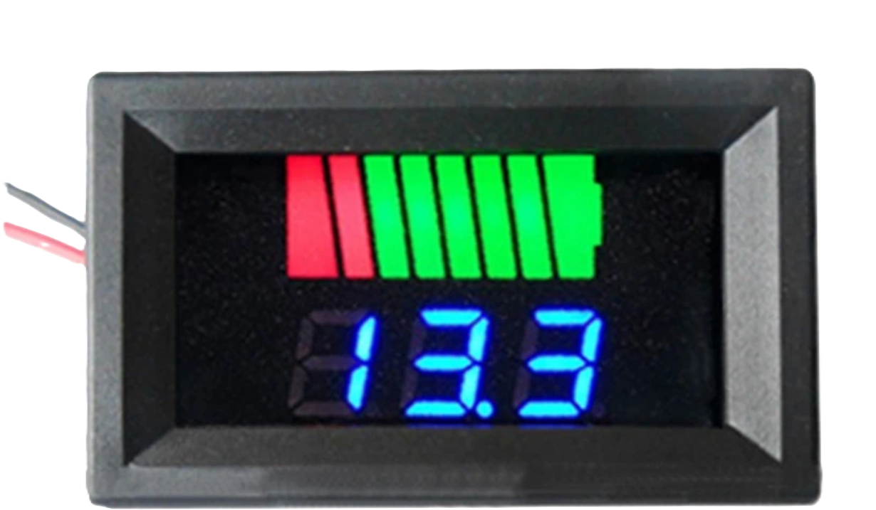
The Indicator Battery Level is an electronic component designed to visually display the current charge level of a battery. It typically uses LEDs, a bar graph, or a gauge to indicate whether the battery is full, half-charged, or low. This component is widely used in portable electronics, power banks, electric vehicles, and renewable energy systems to provide users with a quick and intuitive understanding of the battery's status.
Explore Projects Built with Indicator battery level
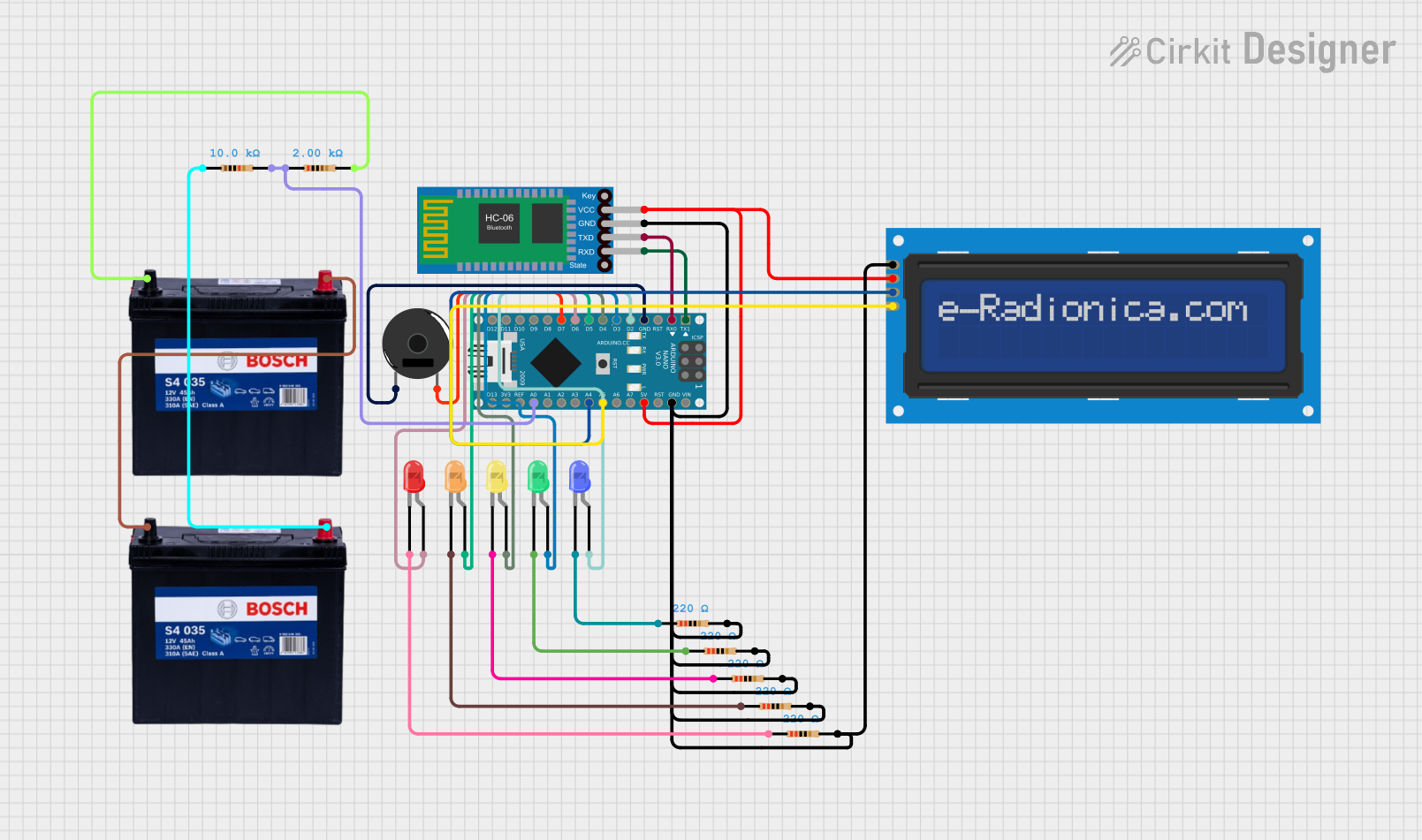

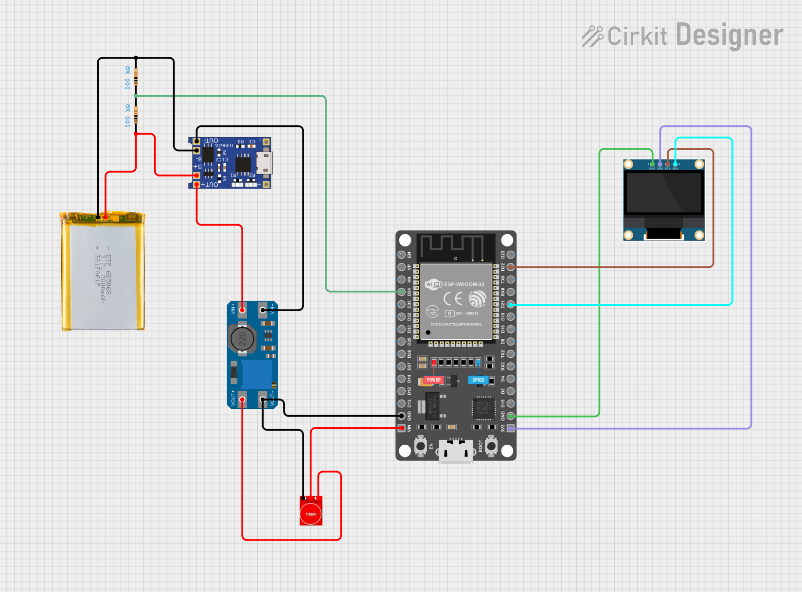
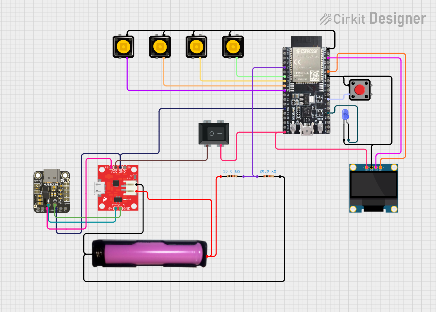
Explore Projects Built with Indicator battery level
Common Applications and Use Cases
- Portable electronic devices (e.g., power banks, flashlights)
- Electric vehicles and scooters
- Solar power systems
- Uninterruptible Power Supplies (UPS)
- Battery management systems (BMS)
Technical Specifications
Below are the general technical specifications for a typical Indicator Battery Level module. Specifications may vary depending on the specific model or manufacturer.
Key Technical Details
- Operating Voltage: 3.7V to 12V (depending on the battery type)
- Current Consumption: Typically 10mA to 50mA
- Display Type: LED bar graph, single LED, or analog gauge
- Battery Compatibility: Lithium-ion, lead-acid, or NiMH batteries
- Measurement Accuracy: ±5% (varies by model)
- Operating Temperature: -10°C to 60°C
Pin Configuration and Descriptions
The pinout for a typical LED-based Indicator Battery Level module is as follows:
| Pin Name | Description |
|---|---|
| VCC | Positive power supply input (connect to the battery's positive terminal). |
| GND | Ground connection (connect to the battery's negative terminal). |
| BAT+ | Battery positive terminal input (used for voltage sensing). |
| BAT- | Battery negative terminal input (used for voltage sensing). |
| LED1-LEDN | Outputs for individual LEDs indicating battery levels (varies by module type). |
Usage Instructions
How to Use the Component in a Circuit
- Connect the Power Supply:
- Connect the
VCCpin to the positive terminal of the battery. - Connect the
GNDpin to the negative terminal of the battery.
- Connect the
- Voltage Sensing:
- Attach the
BAT+andBAT-pins to the battery terminals for accurate voltage measurement.
- Attach the
- LED Outputs:
- If the module has individual LED outputs (e.g.,
LED1,LED2, etc.), connect LEDs to these pins with appropriate current-limiting resistors.
- If the module has individual LED outputs (e.g.,
- Mounting:
- Secure the module in a visible location for easy monitoring of the battery level.
Important Considerations and Best Practices
- Voltage Range: Ensure the module's operating voltage matches the battery's voltage range.
- Current Limiting: Use resistors with LEDs to prevent overcurrent damage.
- Calibration: Some modules may require calibration to accurately reflect battery levels.
- Polarity: Double-check connections to avoid reversing polarity, which can damage the module.
- Environmental Conditions: Avoid exposing the module to extreme temperatures or moisture.
Example: Using with an Arduino UNO
The Indicator Battery Level module can be connected to an Arduino UNO for additional functionality, such as triggering alerts when the battery is low. Below is an example code snippet:
// Example code to monitor battery level using an Indicator Battery Level module
// and an Arduino UNO. The module's BAT+ pin is connected to A0 on the Arduino.

const int batteryPin = A0;  // Analog pin connected to BAT+ of the module
const int lowBatteryLED = 13;  // Digital pin for low battery warning LED

void setup() {
  pinMode(lowBatteryLED, OUTPUT);  // Set the warning LED pin as output
  Serial.begin(9600);  // Initialize serial communication for debugging
}

void loop() {
  int sensorValue = analogRead(batteryPin);  // Read the battery voltage
  float batteryVoltage = sensorValue * (5.0 / 1023.0);  // Convert to voltage

  Serial.print("Battery Voltage: ");
  Serial.println(batteryVoltage);  // Print the voltage to the Serial Monitor

  // Check if the battery voltage is below a threshold (e.g., 3.3V)
  if (batteryVoltage < 3.3) {
    digitalWrite(lowBatteryLED, HIGH);  // Turn on the warning LED
  } else {
    digitalWrite(lowBatteryLED, LOW);  // Turn off the warning LED
  }

  delay(1000);  // Wait for 1 second before the next reading
}
Troubleshooting and FAQs
Common Issues and Solutions
LEDs Not Lighting Up:
- Cause: Incorrect wiring or insufficient power supply.
- Solution: Verify all connections and ensure the battery voltage is within the module's operating range.
Inaccurate Battery Level Indication:
- Cause: Module not calibrated for the specific battery type.
- Solution: Check the module's documentation for calibration instructions or adjust the voltage divider circuit if applicable.
Module Overheating:
- Cause: Excessive current draw or incorrect connections.
- Solution: Use appropriate resistors with LEDs and double-check the wiring.
No Output from the Module:
- Cause: Reversed polarity or damaged module.
- Solution: Ensure correct polarity and replace the module if necessary.
FAQs
Q1: Can this module be used with a 24V battery system?
A1: Most Indicator Battery Level modules are designed for 3.7V to 12V systems. For 24V systems, use a compatible module or a voltage divider circuit.
Q2: How do I know if the module is compatible with my battery?
A2: Check the module's operating voltage range and ensure it matches your battery's voltage.
Q3: Can I use this module to monitor multiple batteries?
A3: No, this module is typically designed to monitor a single battery. For multiple batteries, use a battery management system (BMS).
Q4: Do I need to calibrate the module?
A4: Some modules may require calibration for accurate readings. Refer to the manufacturer's instructions for details.