How to Use ICSP PINS: Examples, Pinouts, and Specs
Introduction
The In-Circuit Serial Programming (ICSP) pins on the Arduino MEGA 2560 are a feature that allows users to program the microcontroller directly through a physical connection. This method is particularly useful for updating the firmware, bypassing the bootloader, or programming the board using an external programmer. ICSP is also used for debugging purposes.
Common applications of ICSP include:
- Programming Arduino boards without a pre-installed bootloader.
- Updating the bootloader on the Arduino.
- Debugging Arduino sketches and hardware.
- Cloning firmware from one Arduino to another.
Explore Projects Built with ICSP PINS

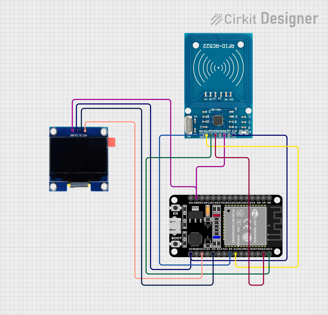

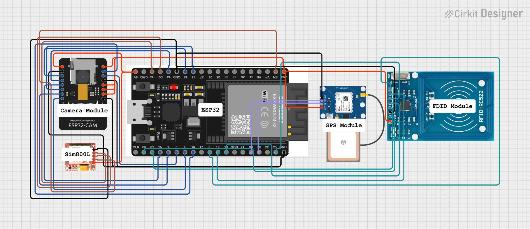
Explore Projects Built with ICSP PINS
Technical Specifications
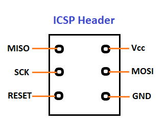
The ICSP header on the Arduino MEGA 2560 consists of a 2x3 pin configuration. The key technical details and pin descriptions are as follows:
| Pin Number | Description | Notes |
|---|---|---|
| 1 | MISO (Master In Slave Out) | Used to receive data from the microcontroller. |
| 2 | VCC | Positive supply voltage, typically +5V. |
| 3 | SCK (Serial Clock) | Clock signal for synchronization. |
| 4 | MOSI (Master Out Slave In) | Used to send data to the microcontroller. |
| 5 | RESET | Used to reset the microcontroller. |
| 6 | GND | Ground connection. |
Usage Instructions
Connecting an External Programmer to the ICSP Header
- Power Off: Ensure that the Arduino MEGA 2560 is powered off before connecting the external programmer.
- Align Pins: Align the programmer's connector with the ICSP header on the Arduino, making sure that the pin 1 indicator (often a small dot or triangle) matches the pin 1 on the board.
- Secure Connection: Gently insert the programmer's connector into the ICSP header. Avoid applying excessive force to prevent bending the pins.
- Power On: Once the programmer is connected, you can power on the Arduino.
Programming the Arduino
To program the Arduino using the ICSP pins:
- Select Programmer: In the Arduino IDE, go to
Tools > Programmerand select the appropriate programmer from the list. - Burn Bootloader: If you need to burn the bootloader, go to
Tools > Burn Bootloader. This step is only necessary if the bootloader is corrupted or if you are using a new microcontroller. - Upload Sketch: To upload a sketch using the ICSP, use the
Upload Using Programmeroption in the Arduino IDE.
Best Practices
- Always verify the pinout and orientation before connecting the programmer to avoid damaging the board.
- Ensure that the external programmer is compatible with the Arduino MEGA 2560.
- Disconnect any power source before making or breaking the ICSP connection.
Troubleshooting and FAQs
Q: What should I do if the Arduino is not responding after using ICSP? A: Check the connections and ensure that the correct programmer is selected in the Arduino IDE. Also, verify that the board is powered.
Q: Can I use the ICSP header to program other devices? A: Yes, the ICSP header can be used to program other compatible microcontrollers or to clone firmware between devices.
Q: How can I tell if my ICSP connection is working? A: When you attempt to program the board, the Arduino IDE will provide feedback. If the programming is successful, you will see a confirmation message. If not, you will receive an error that can help diagnose the issue.
Common Issues and Solutions:
- Incorrect Pin Alignment: Double-check the pin orientation and ensure that pin 1 on the programmer matches pin 1 on the ICSP header.
- Faulty Cables or Connectors: Inspect the cables and connectors for any signs of damage and ensure a secure connection.
- Power Issues: Verify that the Arduino board is receiving power and that the power LED is lit.
For further assistance, consult the Arduino community forums or the official Arduino troubleshooting guide.
Example Code for Arduino UNO
While the ICSP pins are primarily used for programming, they can also be used for SPI communication. Below is an example of how to use the ICSP header for SPI communication with an Arduino UNO. The same principles apply to the Arduino MEGA 2560.
#include <SPI.h>

void setup() {
  // Set the SPI settings
  SPI.begin();
  SPI.setClockDivider(SPI_CLOCK_DIV16); // Adjust as needed
}

void loop() {
  // Start the SPI transaction
  SPI.beginTransaction(SPISettings(14000000, MSBFIRST, SPI_MODE0));
  digitalWrite(SS, LOW); // Pull SS low to prep other device for SPI data

  // Send a byte
  SPI.transfer(0x42); // Replace with the actual data byte

  digitalWrite(SS, HIGH); // Pull SS high to signify end of data transfer
  SPI.endTransaction(); // End the SPI transaction

  delay(1000); // Wait for a second
}
Remember to connect the SS (Slave Select) pin to the appropriate device you are communicating with. The SS pin is not part of the ICSP header and must be defined separately.