How to Use DC-DC Step Up Boost Power Converter: Examples, Pinouts, and Specs
Introduction
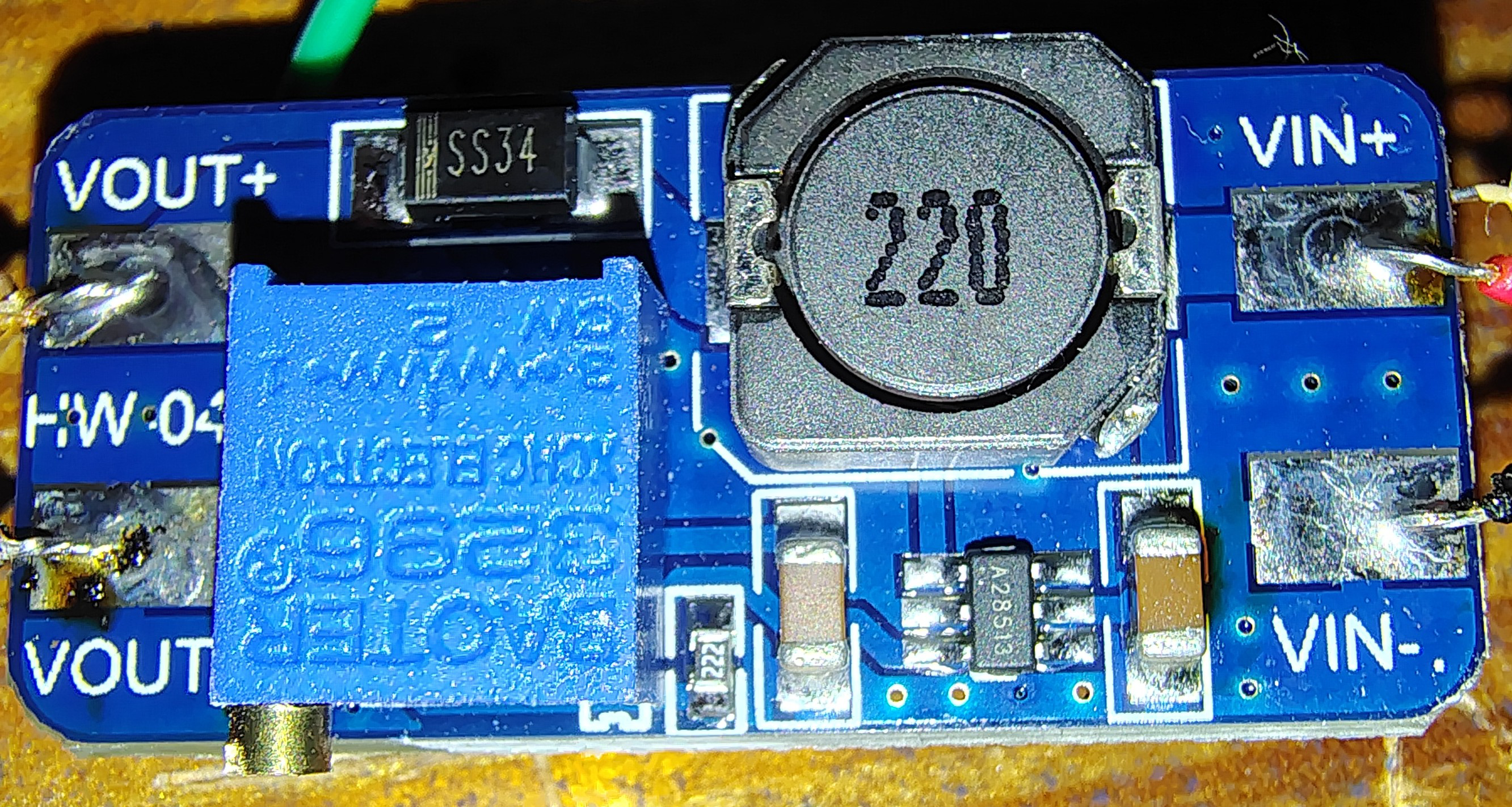
The DC-DC Step Up Boost Power Converter (MT3608), manufactured by Dorhea, is a compact and efficient electronic module designed to increase a lower input voltage to a higher output voltage. This boost converter is based on the MT3608 chip and is widely used in applications requiring voltage step-up, such as powering devices from batteries, portable electronics, and DIY projects.
Explore Projects Built with DC-DC Step Up Boost Power Converter


Explore Projects Built with DC-DC Step Up Boost Power Converter
Common Applications and Use Cases
- Powering 5V devices from 3.7V lithium-ion batteries
- LED lighting systems
- Portable power banks
- Arduino and microcontroller projects
- Solar-powered systems
- Wireless communication modules
Technical Specifications
The following table outlines the key technical details of the MT3608 DC-DC Step Up Boost Power Converter:
| Parameter | Specification |
|---|---|
| Input Voltage Range | 2V to 24V |
| Output Voltage Range | 5V to 28V (adjustable via potentiometer) |
| Maximum Output Current | 2A (recommended ≤ 1.5A for stable operation) |
| Efficiency | Up to 93% |
| Switching Frequency | 1.2 MHz |
| Dimensions | 36mm x 17mm x 6mm |
| Operating Temperature | -40°C to +85°C |
Pin Configuration and Descriptions
The MT3608 module has the following pin layout:
| Pin Name | Description |
|---|---|
| VIN | Positive input voltage terminal (2V to 24V) |
| GND | Ground terminal (common ground for input and output) |
| VOUT | Positive output voltage terminal (5V to 28V) |
Usage Instructions
How to Use the Component in a Circuit
Connect the Input Voltage:
- Connect the positive terminal of your power source (e.g., battery) to the VIN pin.
- Connect the negative terminal of your power source to the GND pin.
Adjust the Output Voltage:
- Use a small screwdriver to turn the onboard potentiometer clockwise to increase the output voltage or counterclockwise to decrease it.
- Measure the output voltage across the VOUT and GND pins using a multimeter to ensure it matches your desired value.
Connect the Load:
- Attach the positive terminal of your load to the VOUT pin.
- Connect the negative terminal of your load to the GND pin.
Power On:
- Turn on the power source and verify the output voltage and current to ensure proper operation.
Important Considerations and Best Practices
- Input Voltage Limit: Ensure the input voltage does not exceed 24V to avoid damaging the module.
- Output Current Limit: Do not exceed 1.5A for continuous operation to maintain stability and prevent overheating.
- Heat Dissipation: If operating at high currents, consider adding a heatsink or active cooling to the module.
- Voltage Adjustment: Always adjust the output voltage without a load connected to prevent damage to sensitive devices.
- Polarity Protection: Double-check the polarity of the input and output connections to avoid irreversible damage.
Example: Using the MT3608 with an Arduino UNO
The MT3608 can be used to power an Arduino UNO from a 3.7V lithium-ion battery. Below is an example circuit and Arduino code:
Circuit Connections
- Connect the battery's positive terminal to VIN and negative terminal to GND.
- Adjust the output voltage to 5V using the potentiometer.
- Connect the VOUT pin to the Arduino's 5V pin and the GND pin to the Arduino's GND pin.
Arduino Code Example
// Example code to blink an LED using an Arduino UNO powered by the MT3608
// Ensure the MT3608 output is set to 5V before connecting to the Arduino

const int ledPin = 13; // Pin connected to the onboard LED

void setup() {
  pinMode(ledPin, OUTPUT); // Set the LED pin as an output
}

void loop() {
  digitalWrite(ledPin, HIGH); // Turn the LED on
  delay(1000);               // Wait for 1 second
  digitalWrite(ledPin, LOW);  // Turn the LED off
  delay(1000);               // Wait for 1 second
}
Troubleshooting and FAQs
Common Issues and Solutions
No Output Voltage:
- Cause: Incorrect input polarity or loose connections.
- Solution: Verify the input polarity and ensure all connections are secure.
Output Voltage Not Adjustable:
- Cause: Faulty potentiometer or incorrect adjustment procedure.
- Solution: Turn the potentiometer slowly and ensure no load is connected during adjustment.
Overheating:
- Cause: Excessive output current or insufficient cooling.
- Solution: Reduce the load current or add a heatsink to the module.
Load Not Powering On:
- Cause: Output voltage too low or insufficient current.
- Solution: Verify the output voltage and ensure it matches the load's requirements.
FAQs
Q1: Can the MT3608 be used to power a Raspberry Pi?
A1: Yes, but ensure the output voltage is set to 5V and the current demand does not exceed 1.5A.
Q2: Is the MT3608 protected against reverse polarity?
A2: No, the module does not have built-in reverse polarity protection. Always double-check your connections.
Q3: Can I use the MT3608 with a solar panel?
A3: Yes, as long as the solar panel's output voltage is within the 2V to 24V range and provides sufficient current.
Q4: How do I measure the output voltage?
A4: Use a multimeter to measure the voltage across the VOUT and GND pins.
By following this documentation, you can effectively use the Dorhea MT3608 DC-DC Step Up Boost Power Converter in your projects.