How to Use DFRobot Camera AI: Examples, Pinouts, and Specs
Introduction
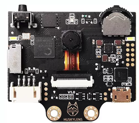
The DFRobot Camera AI is a smart camera module equipped with advanced artificial intelligence (AI) capabilities. It is designed for image recognition, object detection, and various computer vision applications. This versatile module is ideal for developers, hobbyists, and researchers looking to integrate AI-powered vision into their projects. With its compact design and powerful processing capabilities, the DFRobot Camera AI is suitable for robotics, IoT devices, smart home systems, and educational projects.
Explore Projects Built with DFRobot Camera AI
Explore Projects Built with DFRobot Camera AI
Common Applications and Use Cases
- Object detection and tracking in robotics
- Face recognition for security systems
- Gesture recognition for interactive devices
- Image classification in IoT applications
- Educational projects involving AI and computer vision
Technical Specifications
The DFRobot Camera AI module is packed with features that make it a powerful tool for AI and computer vision tasks. Below are the key technical specifications:
| Specification | Details |
|---|---|
| Processor | AI-enabled microcontroller with integrated neural network acceleration |
| Camera Resolution | 2MP (1920x1080) |
| Communication Interfaces | UART, I2C, SPI |
| Input Voltage | 3.3V to 5V |
| Power Consumption | < 200mA |
| Storage | MicroSD card slot (up to 32GB) |
| Dimensions | 40mm x 40mm x 15mm |
| Operating Temperature | -20°C to 70°C |
Pin Configuration and Descriptions
The DFRobot Camera AI module features a standard pinout for easy integration into various systems. Below is the pin configuration:
| Pin | Name | Description |
|---|---|---|
| 1 | VCC | Power input (3.3V to 5V) |
| 2 | GND | Ground |
| 3 | TX | UART Transmit |
| 4 | RX | UART Receive |
| 5 | SDA | I2C Data Line |
| 6 | SCL | I2C Clock Line |
| 7 | CS | SPI Chip Select |
| 8 | MOSI | SPI Master Out Slave In |
| 9 | MISO | SPI Master In Slave Out |
| 10 | SCK | SPI Clock |
| 11 | RESET | Reset pin for the module |
| 12 | GPIO | General-purpose input/output pin for custom use |
Usage Instructions
How to Use the Component in a Circuit
- Power the Module: Connect the VCC pin to a 3.3V or 5V power source and the GND pin to ground.
- Choose a Communication Interface: Depending on your application, connect the UART, I2C, or SPI pins to your microcontroller or development board.
- Connect Additional Peripherals: If needed, insert a microSD card for storing images or data.
- Initialize the Module: Use the appropriate library or firmware to initialize the DFRobot Camera AI and configure its settings.
Important Considerations and Best Practices
- Ensure the power supply is stable and within the specified voltage range to avoid damage to the module.
- Use proper pull-up resistors for I2C communication if required by your setup.
- Avoid exposing the camera lens to direct sunlight or harsh environmental conditions to maintain image quality.
- Update the firmware regularly to access the latest features and improvements.
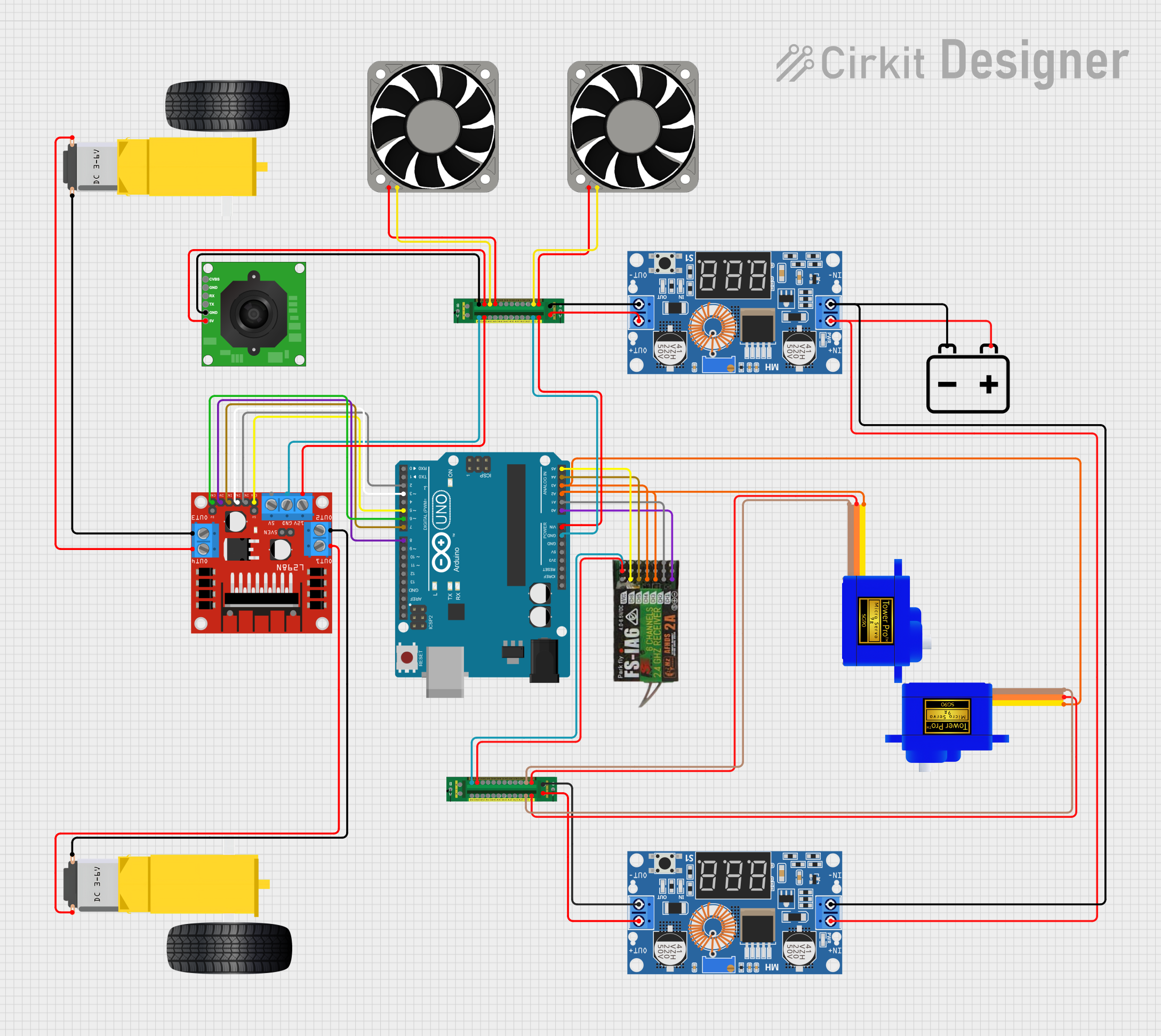
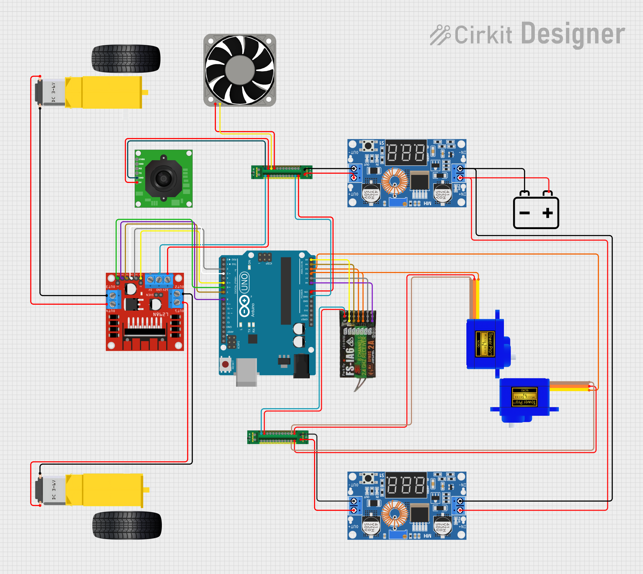
Example: Using the DFRobot Camera AI with Arduino UNO
Below is an example of how to connect and use the DFRobot Camera AI with an Arduino UNO via UART:
Circuit Connections
- Connect the VCC pin of the camera to the 5V pin on the Arduino.
- Connect the GND pin of the camera to the GND pin on the Arduino.
- Connect the TX pin of the camera to the RX pin on the Arduino.
- Connect the RX pin of the camera to the TX pin on the Arduino.
Arduino Code
#include <SoftwareSerial.h>

// Define the RX and TX pins for SoftwareSerial
SoftwareSerial CameraAI(10, 11); // RX = pin 10, TX = pin 11

void setup() {
  Serial.begin(9600); // Initialize Serial Monitor
  CameraAI.begin(115200); // Initialize communication with the camera

  Serial.println("Initializing DFRobot Camera AI...");
  delay(1000);

  // Send a test command to the camera
  CameraAI.println("AT+INIT");
  delay(500);

  // Check for a response from the camera
  if (CameraAI.available()) {
    String response = CameraAI.readString();
    Serial.println("Camera Response: " + response);
  } else {
    Serial.println("No response from the camera. Check connections.");
  }
}

void loop() {
  // Continuously read data from the camera
  if (CameraAI.available()) {
    String data = CameraAI.readString();
    Serial.println("Camera Data: " + data);
  }
}
Notes:
- Replace
AT+INITwith the appropriate command for your specific application. - Ensure the baud rate matches the default setting of the DFRobot Camera AI.
Troubleshooting and FAQs
Common Issues and Solutions
No Response from the Camera
- Cause: Incorrect wiring or communication settings.
- Solution: Double-check the connections and ensure the baud rate matches the camera's default setting.
Blurry or Low-Quality Images
- Cause: Dirty or damaged camera lens.
- Solution: Clean the lens with a soft, lint-free cloth. Avoid touching the lens directly.
Module Overheating
- Cause: Prolonged use in high-temperature environments.
- Solution: Ensure proper ventilation and avoid using the module in temperatures exceeding 70°C.
I2C or SPI Communication Fails
- Cause: Missing pull-up resistors or incorrect pin connections.
- Solution: Add appropriate pull-up resistors for I2C and verify the SPI connections.
FAQs
Can the DFRobot Camera AI be used with Raspberry Pi?
- Yes, the module can be connected to a Raspberry Pi using UART, I2C, or SPI interfaces.
What is the maximum frame rate of the camera?
- The maximum frame rate depends on the resolution and processing load but typically ranges from 15 to 30 FPS.
Does the module support custom AI models?
- Yes, you can upload custom AI models to the module using the provided tools and documentation from DFRobot.
Is the module compatible with other microcontrollers?
- Yes, the DFRobot Camera AI is compatible with most microcontrollers that support UART, I2C, or SPI communication.
By following this documentation, you can effectively integrate the DFRobot Camera AI into your projects and leverage its powerful AI capabilities.