How to Use Array Sensor: Examples, Pinouts, and Specs
Introduction
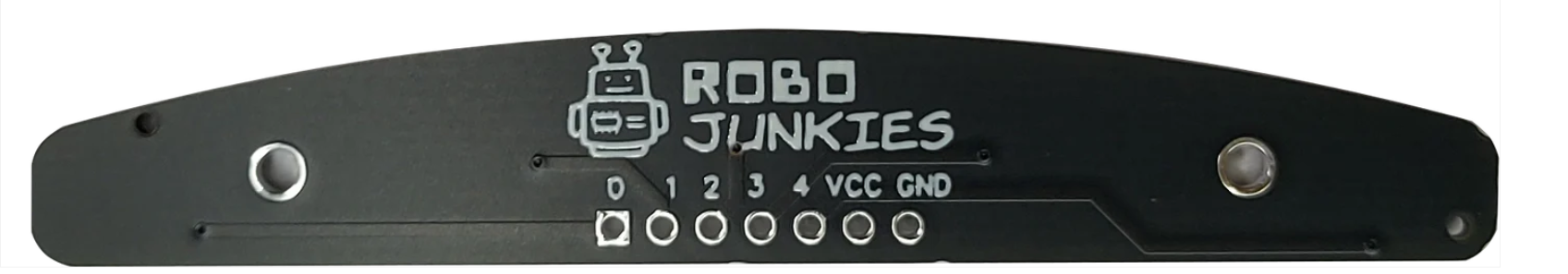
An array sensor is an electronic component designed to detect or measure multiple inputs simultaneously. It is composed of an array of individual sensor elements, typically arranged in a grid pattern. This configuration allows the sensor to capture data from multiple points or directions concurrently, making it ideal for applications that require spatial awareness or detailed environmental analysis.
Explore Projects Built with Array Sensor
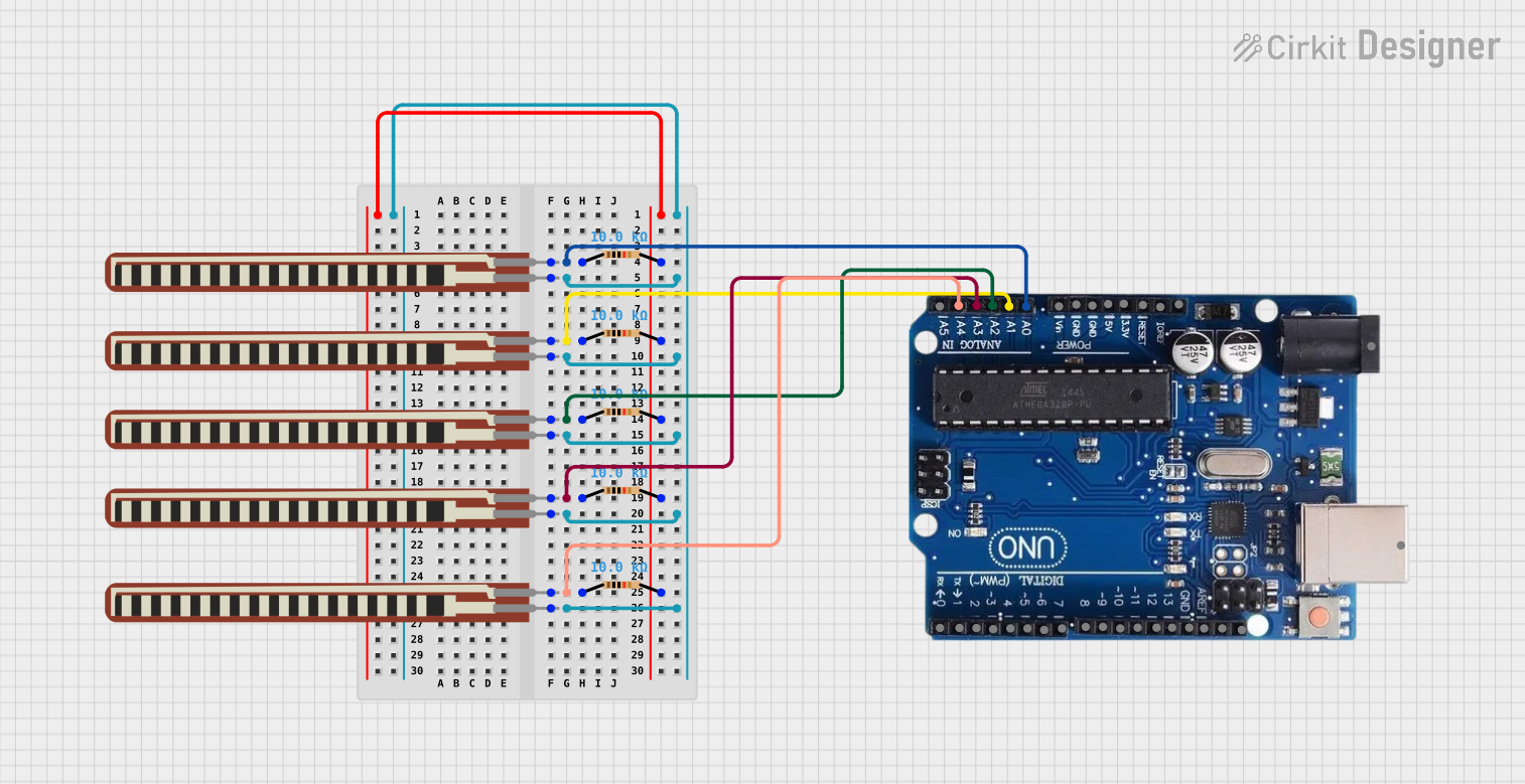

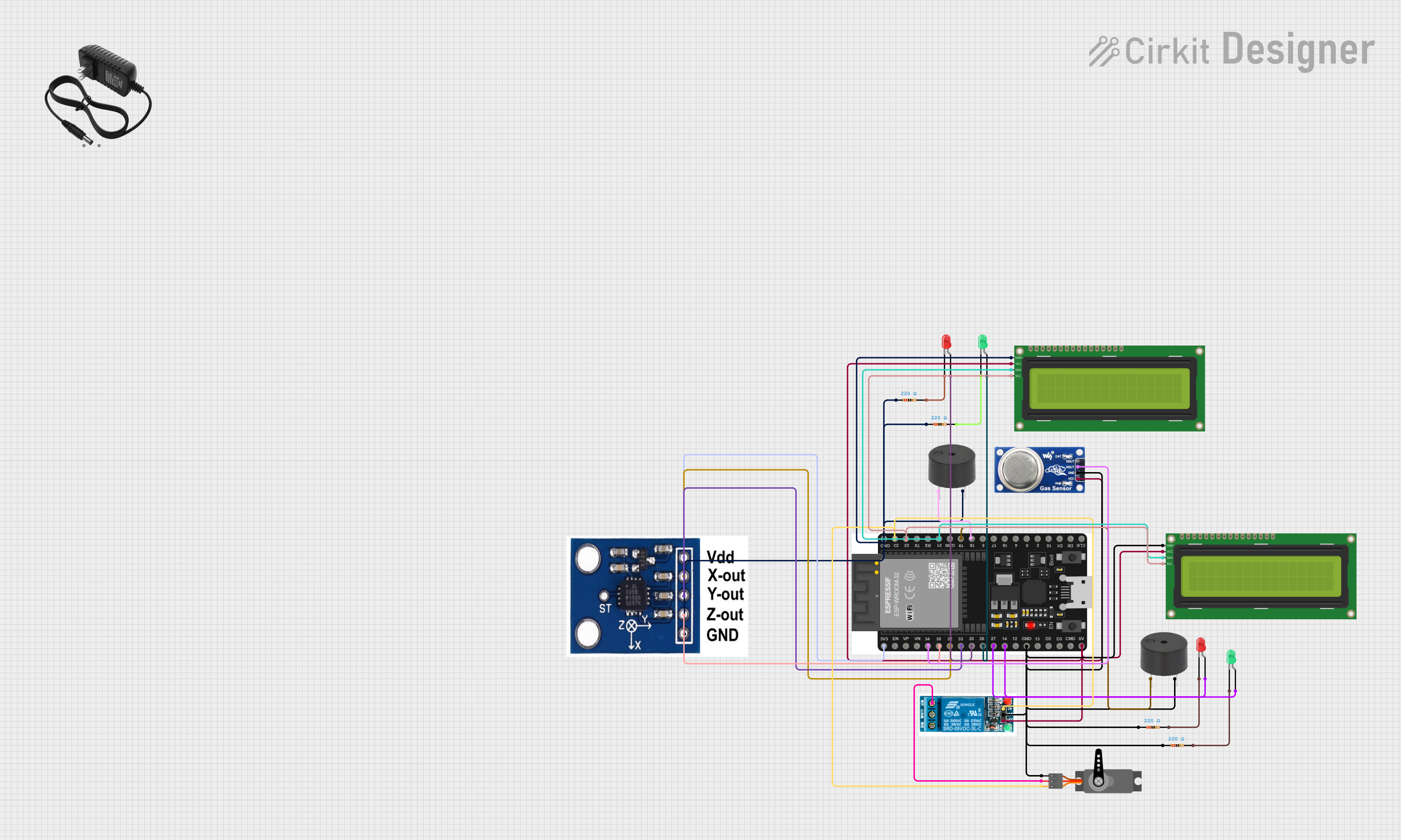
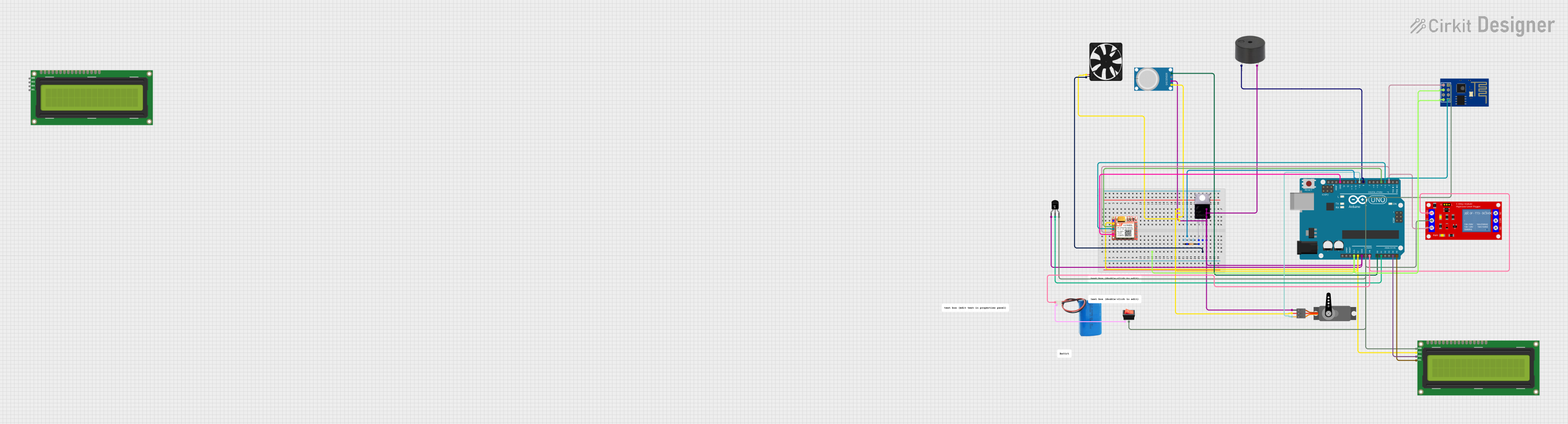
Explore Projects Built with Array Sensor
Common Applications and Use Cases
- Robotics: For obstacle detection and navigation.
- Medical Imaging: In devices such as CT scanners and digital X-ray sensors.
- Consumer Electronics: In touch screens and fingerprint scanners.
- Industrial Automation: For product inspection and quality control.
- Environmental Monitoring: To measure various environmental parameters over a large area.
Technical Specifications
Key Technical Details
- Operating Voltage: 3.3V - 5V
- Current Consumption: 10mA (typical)
- Sensing Range: Dependent on individual sensor elements
- Output Type: Analog/Digital (model specific)
- Interface: I2C/SPI (model specific)
Pin Configuration and Descriptions
| Pin Number | Name | Description |
|---|---|---|
| 1 | VCC | Power supply (3.3V - 5V) |
| 2 | GND | Ground connection |
| 3 | SDA | I2C Data Line (if I2C interface) |
| 4 | SCL | I2C Clock Line (if I2C interface) |
| 5 | MISO | SPI Master In Slave Out (if SPI interface) |
| 6 | MOSI | SPI Master Out Slave In (if SPI interface) |
| 7 | SCK | SPI Serial Clock (if SPI interface) |
| 8 | CS | SPI Chip Select (if SPI interface) |
| 9-n | OUT | Analog or Digital output (model specific) |
Usage Instructions
How to Use the Component in a Circuit
- Power Supply: Connect the VCC pin to a power source within the specified operating voltage range and the GND pin to the ground of your circuit.
- Data Interface: Depending on the model, connect the SDA and SCL pins for I2C communication or the MISO, MOSI, SCK, and CS pins for SPI communication.
- Output: Connect the OUT pins to the input pins of your microcontroller or data acquisition system.
Important Considerations and Best Practices
- Ensure that the power supply is stable and within the specified voltage range to prevent damage.
- Use pull-up resistors on the I2C data and clock lines if they are not built into the sensor.
- For SPI communication, ensure that the CS pin is toggled correctly to enable and disable the sensor.
- Avoid placing the sensor in environments that exceed its specified temperature and humidity ranges.
- When placing multiple array sensors close to each other, ensure there is no crosstalk or interference.
Troubleshooting and FAQs
Common Issues
- No Data Output: Check power supply connections and ensure proper communication protocol setup.
- Inaccurate Readings: Verify that the sensor is calibrated correctly and not subjected to environmental factors outside its specified range.
Solutions and Tips for Troubleshooting
- Double-check wiring and solder joints for any loose connections or shorts.
- Use oscilloscope or logic analyzer to confirm that communication signals are being transmitted and received correctly.
- Consult the sensor's datasheet for any specific calibration procedures or diagnostic modes.
FAQs
Q: Can the array sensor be used with an Arduino UNO? A: Yes, the array sensor can be interfaced with an Arduino UNO using either I2C or SPI, depending on the model.
Q: What is the maximum distance the sensor can measure? A: The maximum sensing range depends on the individual sensor elements and their configuration. Refer to the specific model's datasheet for details.
Q: How can I increase the sensor's resolution? A: The resolution is determined by the number and density of sensor elements. To increase resolution, choose a model with a higher number of elements or a finer grid pattern.
Example Arduino UNO Code
Below is an example of how to interface an array sensor with an Arduino UNO using the I2C protocol:
#include <Wire.h>

// Define the I2C address of the array sensor (check datasheet)
#define SENSOR_I2C_ADDRESS 0xXX

void setup() {
  Wire.begin(); // Initialize I2C communication
  Serial.begin(9600); // Start serial communication at 9600 baud rate
}

void loop() {
  Wire.beginTransmission(SENSOR_I2C_ADDRESS);
  // Request a reading from the sensor
  Wire.requestFrom(SENSOR_I2C_ADDRESS, 2); // Replace '2' with the number of bytes to read
  if (Wire.available()) {
    // Read the bytes returned by the sensor
    byte data1 = Wire.read();
    byte data2 = Wire.read();
    // Process the data (depends on the sensor's output format)
  }
  Wire.endTransmission();

  // Add a delay between readings
  delay(1000);
}
Remember to replace 0xXX with the actual I2C address of your array sensor, and adjust the number of bytes to read based on the sensor's output format. The processing of the data will depend on the specific application and the sensor's datasheet.
This documentation provides a foundational understanding of the array sensor and how to integrate it into various applications. For more detailed information, always refer to the manufacturer's datasheet.