
How to Use FS-iA6B : Examples, Pinouts, and Specs
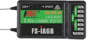
 Design with FS-iA6B in Cirkit Designer
Introduction
The FS-iA6B is a 6-channel receiver manufactured by FlySky, designed for use in remote control systems, particularly in model aircraft, drones, and other RC vehicles. Operating on the 2.4GHz frequency band, it utilizes the AFHDS 2A (Automatic Frequency Hopping Digital System) protocol to ensure a reliable and interference-free connection. Known for its compact size, lightweight design, and robust performance, the FS-iA6B is a popular choice among hobbyists and professionals alike.
Explore Projects Built with FS-iA6B
 Open Project in Cirkit Designer
 Open Project in Cirkit Designer
 Open Project in Cirkit Designer
 Open Project in Cirkit Designer
Explore Projects Built with FS-iA6B
Open Project in Cirkit DesignerOpen Project in Cirkit DesignerOpen Project in Cirkit DesignerOpen Project in Cirkit DesignerCommon Applications and Use Cases
- Remote-controlled aircraft, drones, and helicopters
- RC cars and boats
- Robotics and automation projects
- Educational and hobbyist RC systems
Technical Specifications
The FS-iA6B receiver is designed to deliver high performance and reliability. Below are its key technical specifications:
| Parameter | Specification |
|---|---|
| Frequency Range | 2.405GHz - 2.475GHz |
| Modulation Type | GFSK (Gaussian Frequency Shift Keying) |
| Protocol | AFHDS 2A |
| Channels | 6 |
| Input Voltage Range | 4.0V - 6.5V |
| Antenna Type | Dual antenna for diversity reception |
| Dimensions | 47mm x 26.2mm x 15mm |
| Weight | 14.9g |
| Range | Up to 500m (line of sight) |
| Bind Port | Yes |
| i-BUS Support | Yes |
| PPM Output | Yes |
| PWM Output | Yes |
Pin Configuration and Descriptions
The FS-iA6B receiver features multiple ports for connecting servos, ESCs, and other components. Below is the pin configuration:
| Pin | Label | Description |
|---|---|---|
| 1 | CH1 | PWM output for Channel 1 |
| 2 | CH2 | PWM output for Channel 2 |
| 3 | CH3 | PWM output for Channel 3 |
| 4 | CH4 | PWM output for Channel 4 |
| 5 | CH5 | PWM output for Channel 5 |
| 6 | CH6 | PWM output for Channel 6 |
| 7 | BIND | Bind port for pairing with the transmitter |
| 8 | i-BUS | i-BUS port for digital communication with devices |
| 9 | PPM | PPM output for connecting to flight controllers |
Usage Instructions
How to Use the FS-iA6B in a Circuit
Binding the Receiver to the Transmitter:
- Connect the bind plug to the BIND port on the receiver.
- Power on the receiver using a compatible power source (e.g., a 5V BEC).
- Put the transmitter into bind mode (refer to your transmitter's manual).
- Once the receiver's LED stops flashing and remains solid, the binding process is complete.
- Remove the bind plug and restart the receiver.
Connecting to Servos or ESCs:
- Connect the servo or ESC signal wires to the appropriate channel pins (CH1 to CH6).
- Ensure the power supply to the receiver is within the specified voltage range (4.0V - 6.5V).
Using i-BUS or PPM Output:
- For digital communication with flight controllers, connect the i-BUS or PPM port to the corresponding input on the flight controller.
- Configure the flight controller software to recognize the input protocol.
Important Considerations and Best Practices
- Always ensure the receiver antenna is positioned at a 90-degree angle for optimal signal reception.
- Avoid placing the receiver near high-power components or metal parts that may cause interference.
- Perform a range test before operating your RC model to ensure a stable connection.
- Use a regulated power supply to prevent damage to the receiver.
Example: Connecting FS-iA6B to an Arduino UNO
The FS-iA6B can be connected to an Arduino UNO using the PPM output for reading channel data. Below is an example code snippet:
#include <PPMReader.h>

// Define the PPM input pin and number of channels
#define PPM_PIN 2
#define NUM_CHANNELS 6

// Create a PPMReader object
PPMReader ppm(PPM_PIN, NUM_CHANNELS);

void setup() {
  Serial.begin(9600); // Initialize serial communication
  Serial.println("FS-iA6B Receiver Test");
}

void loop() {
  // Read and print the values of all channels
  for (int channel = 1; channel <= NUM_CHANNELS; channel++) {
    int value = ppm.latestValidChannelValue(channel, 0);
    Serial.print("Channel ");
    Serial.print(channel);
    Serial.print(": ");
    Serial.println(value);
  }
  delay(100); // Delay to avoid flooding the serial monitor
}
Note: Connect the PPM output pin of the FS-iA6B to pin 2 of the Arduino UNO. Ensure the receiver is powered correctly.
Troubleshooting and FAQs
Common Issues and Solutions
Receiver Not Binding to Transmitter:
- Ensure the transmitter is in bind mode and supports the AFHDS 2A protocol.
- Check that the bind plug is securely connected to the BIND port.
- Verify that the receiver is powered within the specified voltage range.
No Signal Output from Channels:
- Confirm that the receiver is properly bound to the transmitter.
- Check the connections between the receiver and servos/ESCs.
- Ensure the transmitter is configured to output signals on the correct channels.
Intermittent Signal Loss:
- Ensure the receiver antennas are positioned correctly and not damaged.
- Avoid operating in areas with high RF interference.
- Perform a range test to verify the connection stability.
FAQs
Q: Can the FS-iA6B be used with other brands of transmitters?
A: The FS-iA6B is compatible only with FlySky transmitters that support the AFHDS 2A protocol.
Q: What is the maximum range of the FS-iA6B?
A: The receiver has a maximum range of up to 500 meters in line-of-sight conditions.
Q: Can I use the FS-iA6B with a flight controller?
A: Yes, the FS-iA6B supports i-BUS and PPM outputs, making it compatible with most flight controllers.
Q: How do I update the firmware of the FS-iA6B?
A: Firmware updates are typically not required for the FS-iA6B. If needed, refer to FlySky's official documentation for update instructions.