How to Use Voltage Reference: Examples, Pinouts, and Specs
Introduction
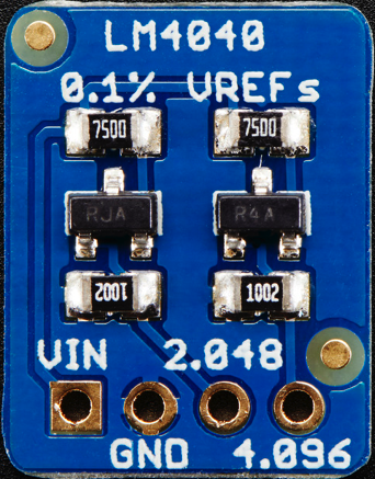
The LM4040 from Adafruit is a precision voltage reference component used in electronic circuits to ensure a stable and accurate voltage level. This fixed, shunt reference voltage device is ideal for converting analog signals to digital, stabilizing sensitive circuits, and providing a reference voltage for analog-to-digital converters (ADCs), digital-to-analog converters (DACs), and other voltage-sensitive components.
Explore Projects Built with Voltage Reference
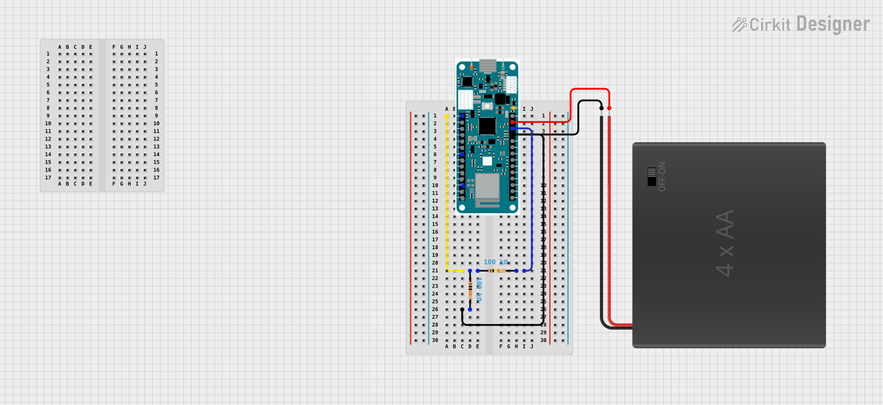

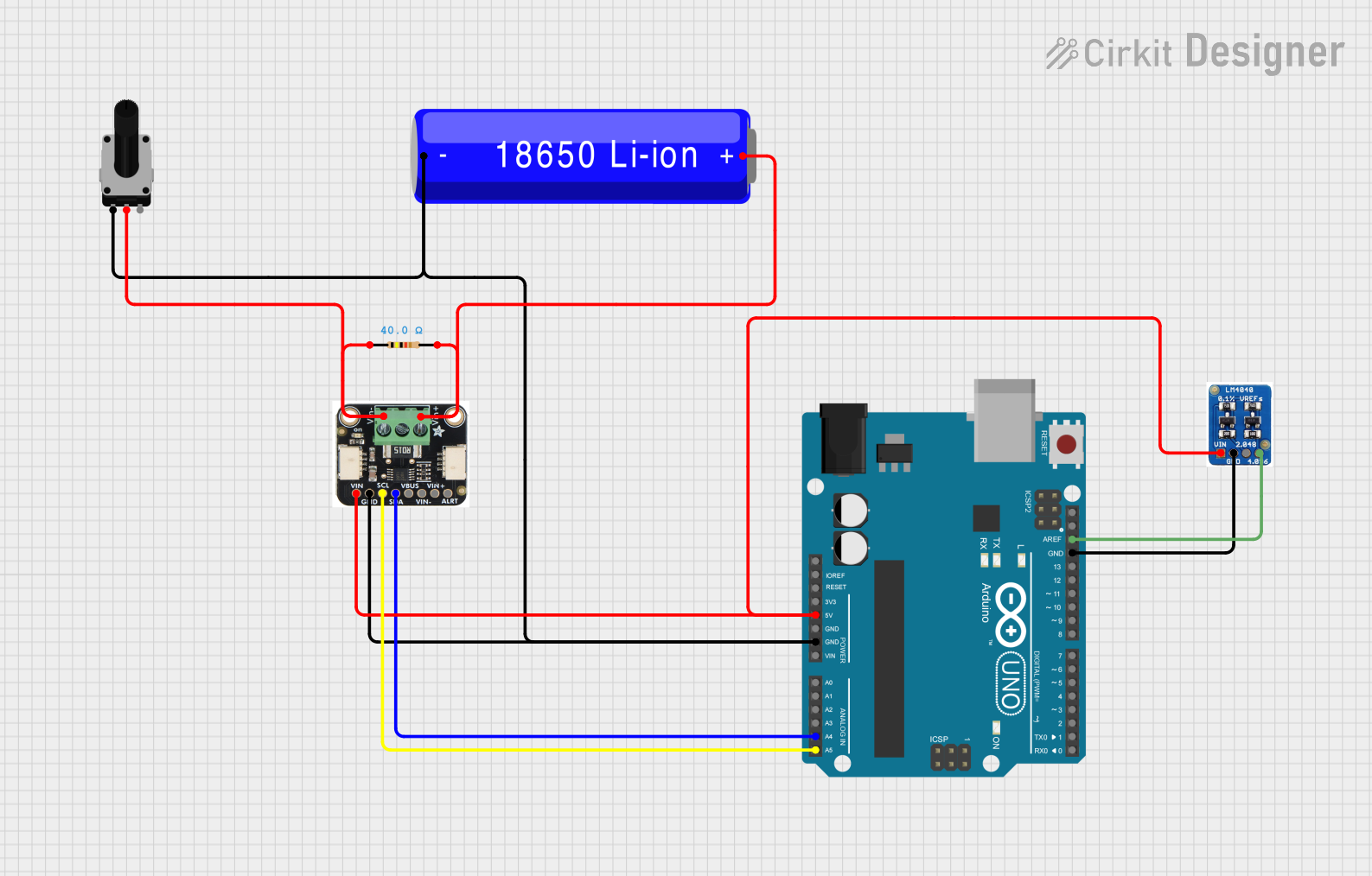
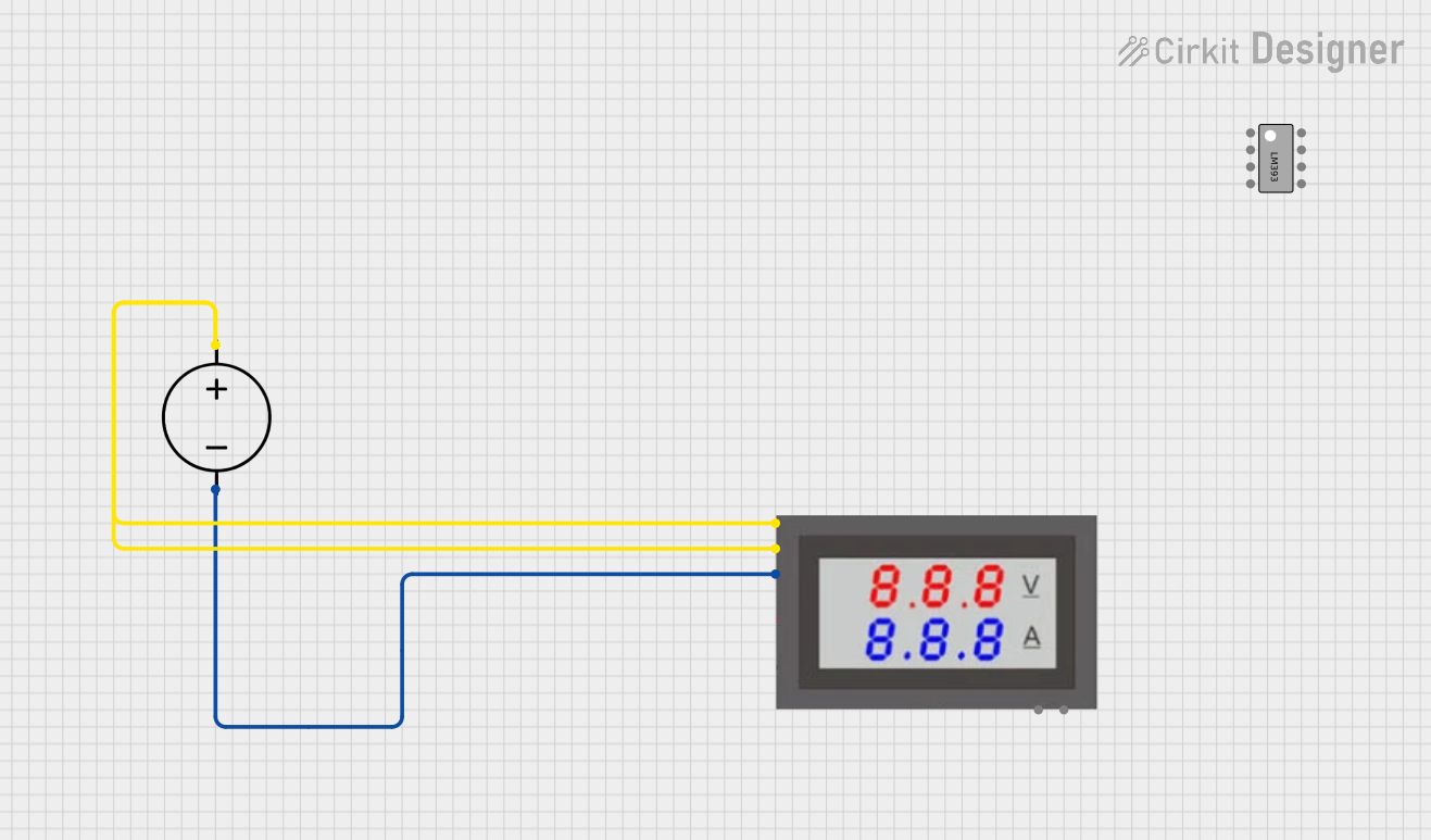
Explore Projects Built with Voltage Reference
Common Applications and Use Cases
- Calibration of measurement devices
- Data acquisition systems
- Battery-powered equipment
- Portable instrumentation
- Voltage monitoring
Technical Specifications
Key Technical Details
- Nominal Voltage: 4.096V
- Initial Accuracy: ±0.1%
- Operating Current: 60µA to 15mA
- Temperature Coefficient: 100ppm/°C
- Operating Temperature Range: -40°C to +85°C
Pin Configuration and Descriptions
| Pin Number | Name | Description |
|---|---|---|
| 1 | ANODE | Connect to the higher potential side of the power supply |
| 2 | CATHODE | Connect to the lower potential side, often ground |
Usage Instructions
How to Use the Component in a Circuit
- Connect the ANODE pin to the positive side of your power supply.
- Connect the CATHODE pin to the ground of your circuit.
- Place a resistor in series with the LM4040 to limit current through the device. The value of the resistor can be calculated using Ohm's law: R = (V_supply - V_reference) / I_operating, where I_operating is the desired operating current.
- Bypass capacitors may be added to the input and output for additional noise reduction.
Important Considerations and Best Practices
- Ensure that the power supply voltage is higher than the nominal voltage of the LM4040.
- Do not exceed the maximum operating current of 15mA.
- The minimum operating current must be greater than 60µA to maintain regulation.
- Avoid exposing the component to temperatures outside the specified operating range.
- Use a stable power supply to minimize the effect of supply voltage variations.
Example Connection with Arduino UNO
// Example code to read analog voltage using LM4040 as a reference

const int analogPin = A0; // Analog input pin connected to the voltage to measure

void setup() {
  Serial.begin(9600);
  analogReference(EXTERNAL); // Set the reference to the external voltage
}

void loop() {
  int sensorValue = analogRead(analogPin); // Read the voltage
  float voltage = sensorValue * (4.096 / 1023.0); // Convert to voltage
  Serial.println(voltage); // Print the voltage to the Serial Monitor
  delay(1000); // Wait for a second
}
In this example, the LM4040 is connected to the AREF pin of the Arduino UNO to provide a precise 4.096V reference voltage for analog readings.
Troubleshooting and FAQs
Common Issues
- Inaccurate Output Voltage: Ensure that the input voltage is sufficient and the current through the device is within the specified range.
- Device Overheating: Check if the current through the LM4040 exceeds the maximum rating or if there's insufficient heat dissipation.
Solutions and Tips for Troubleshooting
- Verify connections and ensure that the ANODE and CATHODE are correctly connected.
- Use a multimeter to measure the voltage across the LM4040 to confirm it is operating at the nominal voltage.
- Check the series resistor value to ensure it is providing the correct operating current.
- Ensure that the power supply is stable and not introducing noise or fluctuations.
FAQs
Q: Can I use the LM4040 with a 5V system? A: Yes, the LM4040 can be used with a 5V system, but ensure that the series resistor limits the current to within the operating range.
Q: What is the purpose of the bypass capacitors? A: Bypass capacitors help filter out noise and provide additional stability to the voltage reference.
Q: How do I choose the value of the series resistor? A: The series resistor value is chosen based on the desired operating current and the difference between the supply voltage and the nominal voltage of the LM4040. Use Ohm's law to calculate the appropriate resistance.
Q: Is calibration required for the LM4040? A: The LM4040 comes with a factory-set precision voltage, so calibration is not typically required. However, system-level calibration may be necessary depending on the application.
For further assistance, please refer to the Adafruit support forums or contact technical support.