How to Use 4x3 Keyboard: Examples, Pinouts, and Specs
Introduction
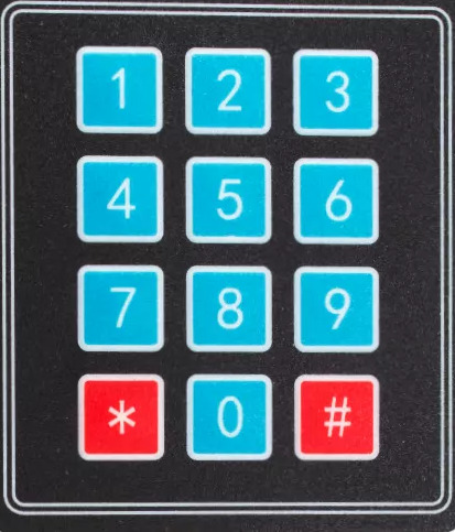
The 4x3 Keyboard (Manufacturer Part ID: Keyboard) is a compact input device manufactured by Arduino. It features a 4x3 matrix of keys, making it ideal for applications requiring a simple and efficient user input interface. This component is commonly used in mobile devices, security systems, calculators, and other electronic projects where numeric or limited alphanumeric input is needed.
Explore Projects Built with 4x3 Keyboard


Explore Projects Built with 4x3 Keyboard
Common Applications and Use Cases
- Keypad entry for security systems (e.g., PIN entry)
- User input for calculators or small devices
- Menu navigation in embedded systems
- Input interface for Arduino-based projects
Technical Specifications
The 4x3 Keyboard is designed to be lightweight and easy to integrate into various electronic systems. Below are its key technical details:
Key Technical Details
| Parameter | Specification |
|---|---|
| Manufacturer | Arduino |
| Part ID | Keyboard |
| Key Matrix | 4 rows x 3 columns |
| Operating Voltage | 3.3V to 5V |
| Maximum Current | 10mA |
| Keypad Dimensions | 70mm x 50mm x 5mm |
| Connector Type | 7-pin header |
| Keypad Material | Plastic with conductive contacts |
Pin Configuration and Descriptions
The 4x3 Keyboard uses a 7-pin interface to connect to a microcontroller. The pins correspond to the rows and columns of the key matrix.
| Pin Number | Pin Name | Description |
|---|---|---|
| 1 | R1 | Row 1 |
| 2 | R2 | Row 2 |
| 3 | R3 | Row 3 |
| 4 | R4 | Row 4 |
| 5 | C1 | Column 1 |
| 6 | C2 | Column 2 |
| 7 | C3 | Column 3 |
Usage Instructions
The 4x3 Keyboard is straightforward to use in electronic circuits. It operates as a matrix, where pressing a key connects a specific row to a specific column. Below are the steps to use the keypad in a circuit:
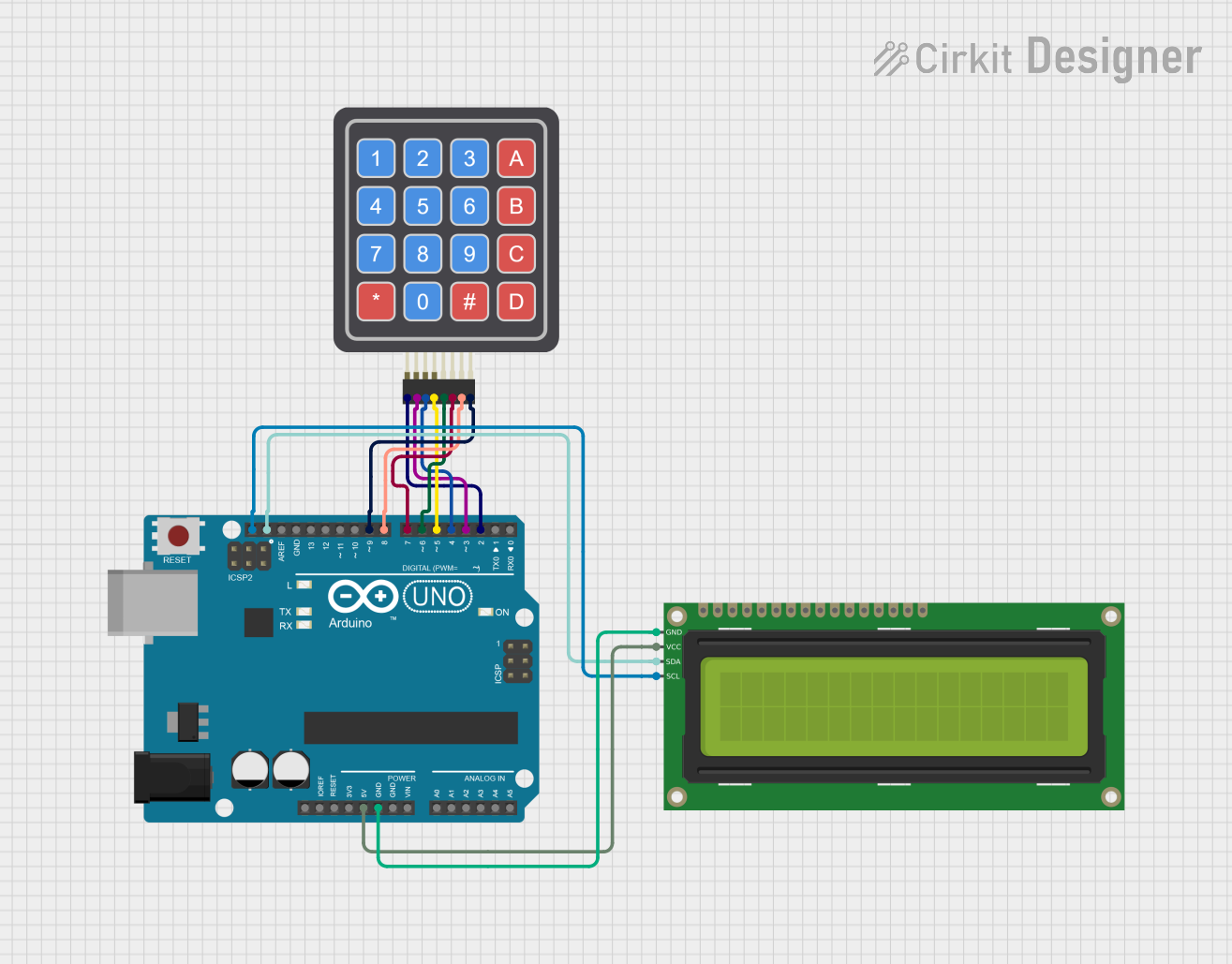
Connecting the 4x3 Keyboard to an Arduino UNO
- Wiring: Connect the 7 pins of the keypad to the Arduino UNO as follows:
- R1 to digital pin 2
- R2 to digital pin 3
- R3 to digital pin 4
- R4 to digital pin 5
- C1 to digital pin 6
- C2 to digital pin 7
- C3 to digital pin 8
- Install the Keypad Library: Use the Arduino IDE Library Manager to install the "Keypad" library.
- Upload the Code: Use the example code below to read key presses.
Example Code
#include <Keypad.h>

// Define the rows and columns of the keypad
const byte ROWS = 4; // Four rows
const byte COLS = 3; // Three columns

// Define the keymap for the keypad
char keys[ROWS][COLS] = {
  {'1', '2', '3'},
  {'4', '5', '6'},
  {'7', '8', '9'},
  {'*', '0', '#'}
};

// Define the row and column pins
byte rowPins[ROWS] = {2, 3, 4, 5}; // Connect to R1, R2, R3, R4
byte colPins[COLS] = {6, 7, 8};    // Connect to C1, C2, C3

// Create the Keypad object
Keypad keypad = Keypad(makeKeymap(keys), rowPins, colPins, ROWS, COLS);

void setup() {
  Serial.begin(9600); // Initialize serial communication
  Serial.println("4x3 Keyboard Test");
}

void loop() {
  char key = keypad.getKey(); // Get the key pressed
  if (key) {
    Serial.print("Key Pressed: ");
    Serial.println(key); // Print the key to the Serial Monitor
  }
}
Important Considerations and Best Practices
- Debouncing: The keypad library handles debouncing, but ensure your code accounts for it if using custom logic.
- Pull-up Resistors: The Arduino's internal pull-up resistors are sufficient for this keypad.
- Power Supply: Ensure the keypad operates within its voltage range (3.3V to 5V).
- Keypad Placement: Avoid placing the keypad in areas exposed to moisture or dust to maintain reliability.
Troubleshooting and FAQs
Common Issues and Solutions
No Key Press Detected
- Cause: Incorrect wiring or loose connections.
- Solution: Double-check the wiring and ensure all connections are secure.
Incorrect Key Detected
- Cause: Mismatched keymap in the code.
- Solution: Verify the keymap matches the physical layout of the keypad.
Multiple Keys Detected Simultaneously
- Cause: Electrical noise or faulty keypad.
- Solution: Ensure proper grounding and test with a different keypad.
Serial Monitor Not Displaying Output
- Cause: Serial communication not initialized or incorrect baud rate.
- Solution: Ensure
Serial.begin(9600)is in thesetup()function and the Serial Monitor is set to 9600 baud.
FAQs
Q: Can I use the 4x3 Keyboard with a 3.3V microcontroller?
A: Yes, the keypad operates within a voltage range of 3.3V to 5V.
Q: How many keys can I press simultaneously?
A: The keypad is designed for single-key detection. Pressing multiple keys may result in undefined behavior.
Q: Can I extend the keypad's cable length?
A: Yes, but longer cables may introduce noise. Use shielded cables if extending beyond 30cm.
Q: Is the keypad waterproof?
A: No, the keypad is not waterproof. Avoid exposure to moisture or liquids.