How to Use L293D: Examples, Pinouts, and Specs

Introduction
The L293D is a quadruple high-current half-H driver designed to provide bidirectional drive currents of up to 600 mA at voltages from 4.5 V to 36 V. It is capable of driving inductive loads such as relays, solenoids, DC, and bipolar stepping motors. Its high current and voltage capabilities make it a popular choice for controlling motors in robotics and automation projects.
Explore Projects Built with L293D
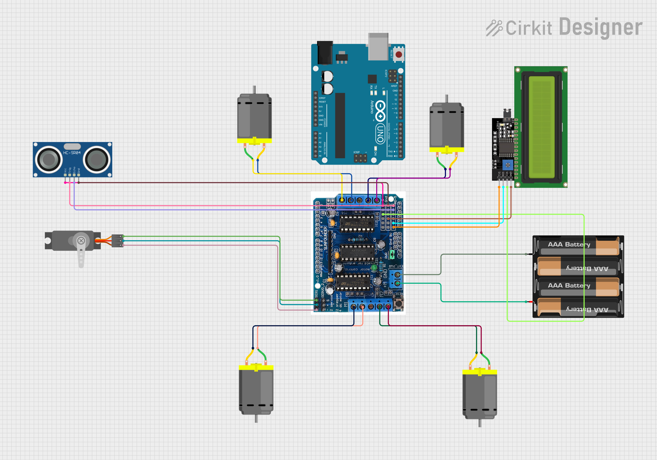

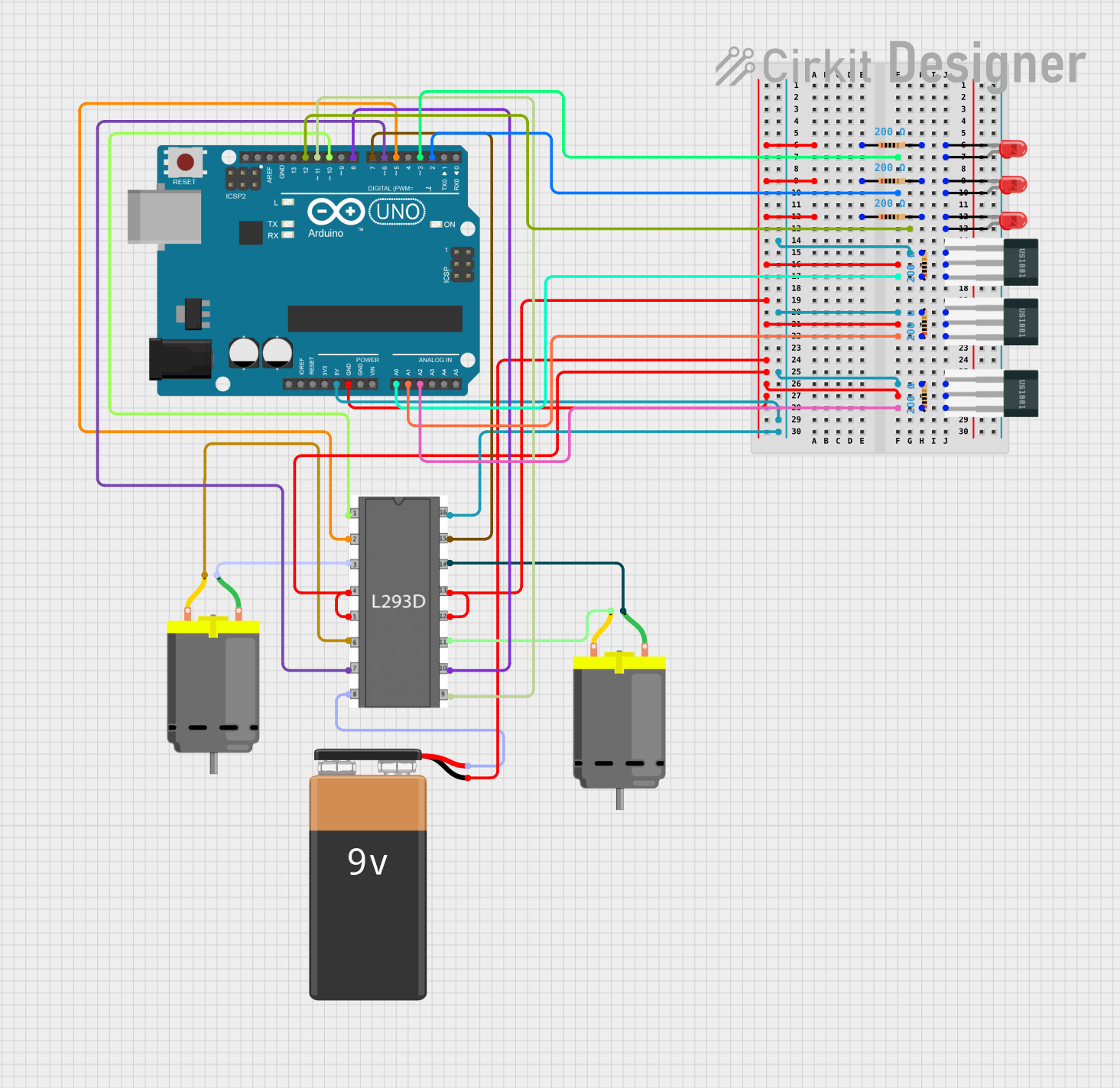
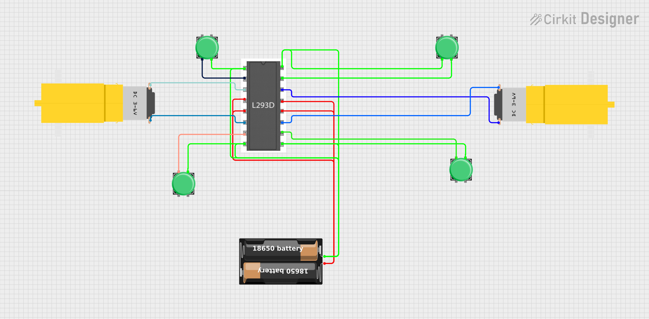
Explore Projects Built with L293D
Common Applications and Use Cases
- Driving small DC motors for robotics
- Controlling stepper motors in 3D printers and CNC machines
- Operating dual motor configurations in remote-controlled vehicles
- Managing solenoids in automated systems
Technical Specifications
Key Technical Details
- Motor Voltage (VM): 4.5V to 36V
- Logic Voltage (VSS): 4.5V to 7V
- Output Current (each channel): 600mA
- Peak Output Current (each channel): 1.2A
- Enable Input Voltage: Up to 7V
- Internal Clamp Diodes: For inductive transient suppression
Pin Configuration and Descriptions
| Pin Number | Name | Description |
|---|---|---|
| 1 | 1,2EN | Enable pin for Motor 1; when high, Motor 1 is enabled |
| 2 | 1A | Input 1 for Motor 1 |
| 3 | 1Y | Output 1 for Motor 1 |
| 4 | GND | Ground |
| 5 | GND | Ground |
| 6 | 2Y | Output 2 for Motor 1 |
| 7 | 2A | Input 2 for Motor 1 |
| 8 | VS | Motor Supply Voltage |
| 9 | 3,4EN | Enable pin for Motor 2; when high, Motor 2 is enabled |
| 10 | 3A | Input 1 for Motor 2 |
| 11 | 3Y | Output 1 for Motor 2 |
| 12 | GND | Ground |
| 13 | GND | Ground |
| 14 | 4Y | Output 2 for Motor 2 |
| 15 | 4A | Input 2 for Motor 2 |
| 16 | VSS | Logic Supply Voltage |
Usage Instructions
How to Use the L293D in a Circuit
- Connect the motor supply voltage (VM) to pin 8, and the logic supply voltage (VSS) to pin 16.
- Ground the IC by connecting pins 4, 5, 12, and 13 to the common ground of the power supply and the microcontroller.
- Connect the enable pins (1,2EN and 3,4EN) to the microcontroller's digital output pins to control the enable state of each motor.
- Connect the input pins (1A, 2A for Motor 1 and 3A, 4A for Motor 2) to the microcontroller's digital output pins to control the direction of the motors.
- Connect the output pins (1Y, 2Y for Motor 1 and 3Y, 4Y for Motor 2) to the motor terminals.
Important Considerations and Best Practices
- Use external diodes for inductive loads to protect the IC from voltage spikes.
- Ensure the power supply can provide sufficient current for the motors.
- Avoid running the IC at its maximum ratings for an extended period to prevent overheating.
- Use heat sinks if operating near the maximum current rating.
Example Code for Arduino UNO
// Define the L293D control pins
#define MOTOR1_EN 9
#define MOTOR1_A 2
#define MOTOR1_B 3

// Initialize the motor control pins
void setup() {
  pinMode(MOTOR1_EN, OUTPUT);
  pinMode(MOTOR1_A, OUTPUT);
  pinMode(MOTOR1_B, OUTPUT);
}

// Function to control motor direction and speed
void motorControl(int speed, boolean reverse) {
  digitalWrite(MOTOR1_EN, HIGH); // Enable the motor
  analogWrite(MOTOR1_A, reverse ? 0 : speed); // Set speed and direction
  analogWrite(MOTOR1_B, reverse ? speed : 0); // Set speed and direction
}

// Main program loop
void loop() {
  motorControl(255, false); // Full speed forward
  delay(2000);              // Run for 2 seconds
  motorControl(255, true);  // Full speed reverse
  delay(2000);              // Run for 2 seconds
}
Troubleshooting and FAQs
Common Issues Users Might Face
- Motor not running: Check if the enable pin is set high and the input pins are correctly configured.
- Insufficient motor speed or torque: Ensure the power supply can deliver enough current and the motor voltage is within the specified range.
- IC overheating: Use a heat sink or reduce the load on the motor.
Solutions and Tips for Troubleshooting
- Verify connections and solder joints for any loose or cold solder points.
- Measure the voltage at the motor terminals to ensure the IC is outputting the correct voltage.
- Check the logic input signals with an oscilloscope or logic analyzer to confirm they are being received by the L293D.
FAQs
Q: Can the L293D drive two motors simultaneously? A: Yes, the L293D can drive two motors at the same time, one connected to outputs 1Y and 2Y, and the other to 3Y and 4Y.
Q: What is the function of the enable pins on the L293D? A: The enable pins allow you to turn the motor outputs on or off. When the enable pin for a motor is high, the motor is enabled and can be controlled by the input pins.
Q: Do I need to use external diodes with the L293D? A: The L293D has built-in clamp diodes for inductive transient suppression. However, for heavy inductive loads, additional external diodes may be used for enhanced protection.