How to Use button sensor module: Examples, Pinouts, and Specs
Introduction
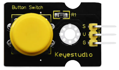
The Keyestudio Button Sensor Module is a simple yet versatile device designed to detect the presence or absence of a button press. It features a push button switch and additional circuitry to provide a clean digital output signal when the button is activated. This module is widely used in projects requiring user input, such as triggering events, controlling devices, or navigating menus in embedded systems.
Explore Projects Built with button sensor module


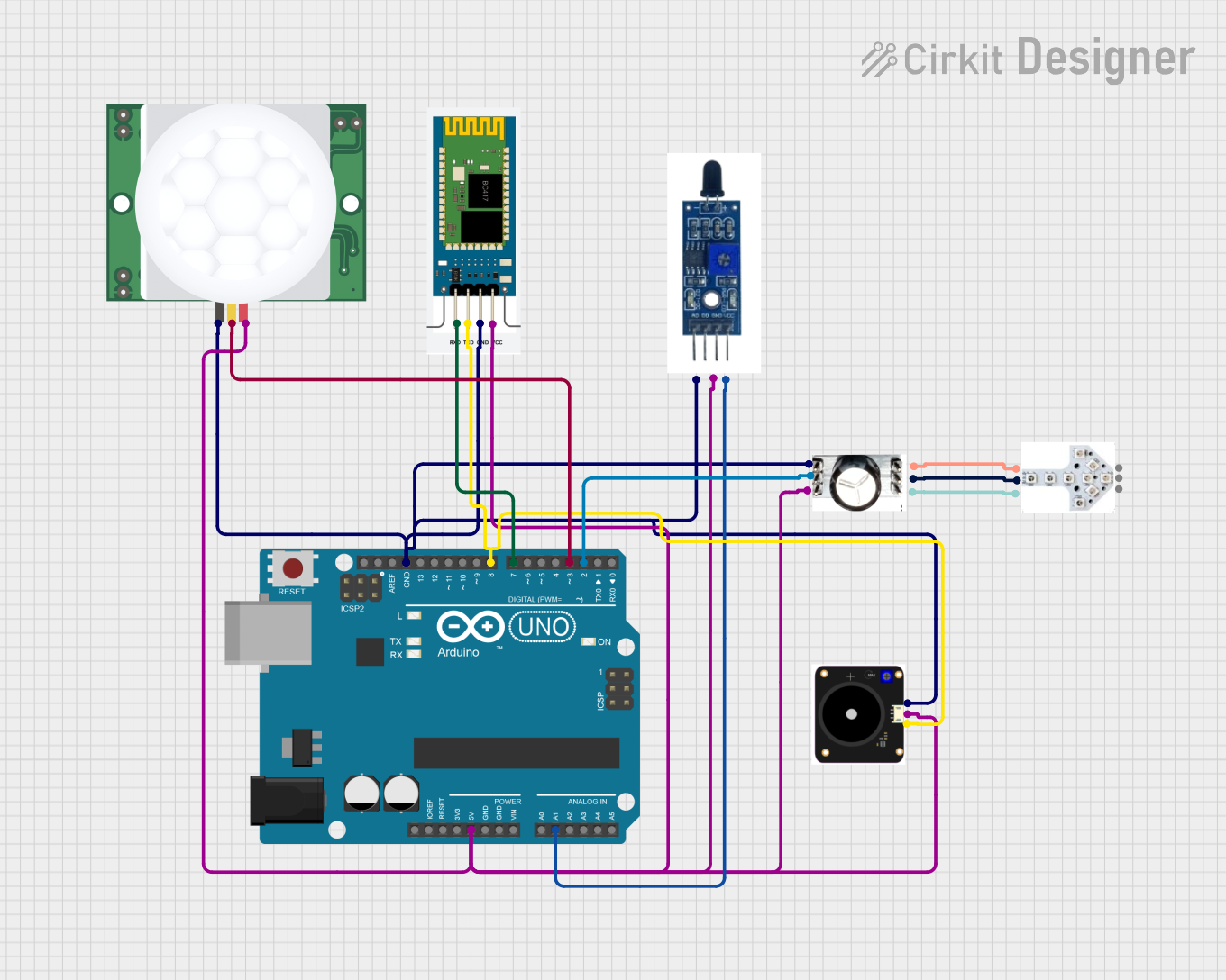
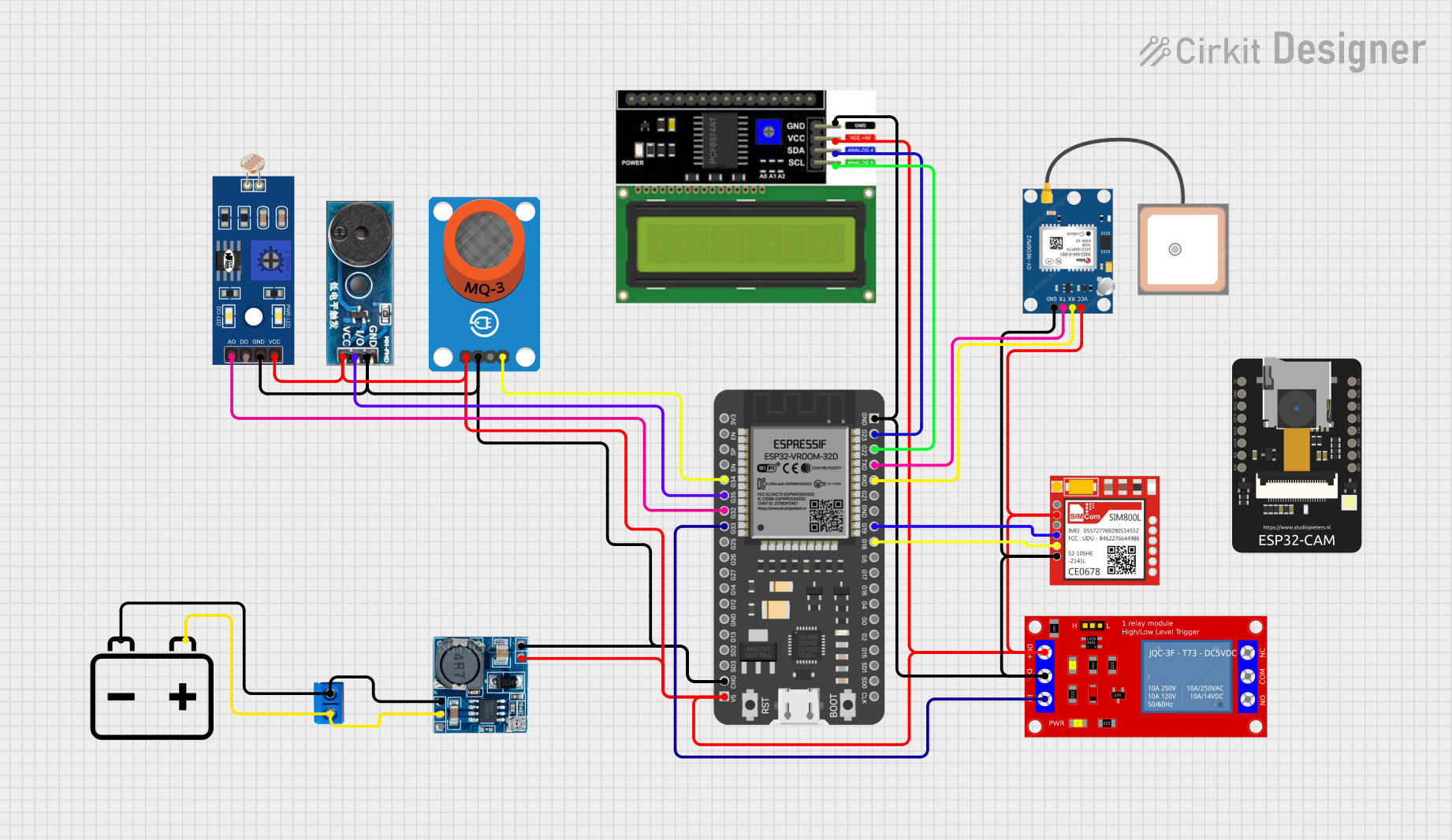
Explore Projects Built with button sensor module
Common Applications and Use Cases
- User input for microcontroller-based projects
- Triggering events in robotics and automation
- Menu navigation in embedded systems
- DIY electronics and prototyping
- Educational projects for learning digital input handling
Technical Specifications
The Keyestudio Button Sensor Module is designed for ease of use and compatibility with a wide range of microcontrollers, including Arduino boards.
Key Technical Details
- Operating Voltage: 3.3V to 5V
- Output Type: Digital (HIGH when pressed, LOW when released)
- Button Type: Momentary push button
- Dimensions: 24mm x 15mm
- Mounting Holes: 2 x M3 holes for secure attachment
- Indicator LED: Onboard LED to indicate button press status
Pin Configuration and Descriptions
The module has a 3-pin interface for easy connection to microcontrollers. Below is the pinout:
| Pin | Label | Description |
|---|---|---|
| 1 | GND | Ground connection |
| 2 | VCC | Power supply (3.3V to 5V) |
| 3 | SIG | Digital signal output (HIGH/LOW) |
Usage Instructions
The Keyestudio Button Sensor Module is straightforward to use in any circuit. Follow the steps below to integrate it into your project:
Connecting the Module
- Power the Module: Connect the
VCCpin to the 3.3V or 5V pin of your microcontroller and theGNDpin to the ground. - Signal Output: Connect the
SIGpin to a digital input pin on your microcontroller.
Example Circuit
- Connect the module's
VCCpin to the Arduino UNO's5Vpin. - Connect the
GNDpin to the Arduino UNO'sGNDpin. - Connect the
SIGpin to digital pin2on the Arduino UNO.
Arduino Code Example
Below is an example Arduino sketch to read the button state and control the onboard LED:
// Define the pin connected to the button sensor module
const int buttonPin = 2; // SIG pin connected to digital pin 2
const int ledPin = 13;   // Onboard LED pin on Arduino UNO

void setup() {
  pinMode(buttonPin, INPUT); // Set button pin as input
  pinMode(ledPin, OUTPUT);  // Set LED pin as output
  Serial.begin(9600);       // Initialize serial communication
}

void loop() {
  int buttonState = digitalRead(buttonPin); // Read the button state

  if (buttonState == HIGH) {
    // If button is pressed, turn on the LED
    digitalWrite(ledPin, HIGH);
    Serial.println("Button Pressed");
  } else {
    // If button is not pressed, turn off the LED
    digitalWrite(ledPin, LOW);
    Serial.println("Button Released");
  }

  delay(100); // Small delay to debounce the button
}
Important Considerations and Best Practices
- Debouncing: Mechanical buttons can produce noise or "bouncing" when pressed. Use a small delay (e.g.,
delay(100)) or implement software debouncing for reliable readings. - Voltage Compatibility: Ensure the module's operating voltage matches your microcontroller's logic level (3.3V or 5V).
- Pull-up Resistor: The module includes an internal pull-up resistor, so no external resistor is required.
Troubleshooting and FAQs
Common Issues and Solutions
No Response from the Button:
- Ensure the module is properly powered (check
VCCandGNDconnections). - Verify the
SIGpin is connected to the correct digital input pin on the microcontroller.
- Ensure the module is properly powered (check
Button Press Not Detected Consistently:
- Add a small delay in the code to debounce the button.
- Check for loose or faulty connections.
Onboard LED Does Not Light Up:
- Confirm the button is being pressed fully.
- Ensure the module is receiving the correct operating voltage.
FAQs
Q: Can I use this module with a Raspberry Pi?
A: Yes, the module is compatible with Raspberry Pi. Connect the SIG pin to a GPIO pin configured as an input, and ensure the operating voltage is 3.3V to avoid damaging the Raspberry Pi.
Q: Does the module work with 3.3V microcontrollers?
A: Yes, the module operates at both 3.3V and 5V, making it compatible with a wide range of microcontrollers.
Q: How do I extend the button's functionality?
A: You can use the button to trigger interrupts, control relays, or navigate menus in your project. Modify the code to suit your specific application.
By following this documentation, you can effectively integrate the Keyestudio Button Sensor Module into your projects and troubleshoot any issues that arise.