How to Use 8 Way Channel Expansion Relay Module 5V Power Supply Optocoupler Isolation Board IIC I2C Communication: Examples, Pinouts, and Specs
Introduction
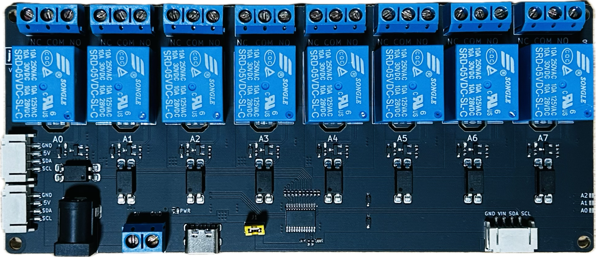
The 8 Way Channel Expansion Relay Module by Songle (Part ID: RELAY) is a versatile and reliable relay module designed for controlling high-power devices using low-power control signals. This module features 8 independent relays, each capable of switching AC or DC loads, making it ideal for home automation, industrial control, and IoT applications. The module is equipped with optocoupler isolation for enhanced safety and noise immunity, and it supports I2C communication for easy integration with microcontrollers like Arduino, Raspberry Pi, and other development boards.
Explore Projects Built with 8 Way Channel Expansion Relay Module 5V Power Supply Optocoupler Isolation Board IIC I2C Communication


Explore Projects Built with 8 Way Channel Expansion Relay Module 5V Power Supply Optocoupler Isolation Board IIC I2C Communication
Common Applications and Use Cases
- Home automation (e.g., controlling lights, fans, and appliances)
- Industrial equipment control
- IoT projects requiring multiple device control
- Robotics and motor control
- Smart energy management systems
Technical Specifications
Key Technical Details
| Parameter | Specification |
|---|---|
| Manufacturer | Songle |
| Part ID | RELAY |
| Operating Voltage | 5V DC |
| Relay Channels | 8 |
| Communication Interface | I2C (IIC) |
| Control Signal Voltage | 3.3V or 5V (logic level compatible) |
| Maximum Load (AC) | 250V AC @ 10A |
| Maximum Load (DC) | 30V DC @ 10A |
| Isolation | Optocoupler isolation |
| Dimensions | 135mm x 55mm x 20mm |
| Mounting | Screw holes for secure installation |
Pin Configuration and Descriptions
Power and Communication Pins
| Pin Name | Description |
|---|---|
| VCC | 5V DC power supply input for the module. |
| GND | Ground connection. |
| SDA | I2C data line for communication with the microcontroller. |
| SCL | I2C clock line for communication with the microcontroller. |
Relay Output Terminals
Each relay channel has three terminals:
| Terminal Name | Description |
|---|---|
| NO (Normally Open) | The relay is open (disconnected) when inactive. Closes when activated. |
| COM (Common) | Common terminal for the relay. |
| NC (Normally Closed) | The relay is closed (connected) when inactive. Opens when activated. |
Usage Instructions
How to Use the Component in a Circuit
- Power the Module: Connect the VCC pin to a 5V DC power source and the GND pin to ground.
- Connect the I2C Interface:
- Connect the SDA pin to the SDA pin of your microcontroller.
- Connect the SCL pin to the SCL pin of your microcontroller.
- Load Connections:
- For each relay, connect the load to the NO (Normally Open) and COM (Common) terminals if you want the load to be off by default.
- Alternatively, use the NC (Normally Closed) and COM terminals if you want the load to be on by default.
- Control the Relays: Use I2C commands from your microcontroller to activate or deactivate the relays.
Important Considerations and Best Practices
- Ensure the total current drawn by the relays does not exceed the power supply's capacity.
- Use proper insulation and safety precautions when working with high-voltage AC loads.
- Avoid switching inductive loads (e.g., motors) without proper flyback diodes or snubber circuits to prevent damage to the relays.
- Double-check the I2C address of the module (default is typically 0x20, but consult the datasheet for confirmation).
Example Code for Arduino UNO
Below is an example code snippet to control the relay module using an Arduino UNO:
#include <Wire.h> // Include the Wire library for I2C communication

#define RELAY_MODULE_ADDRESS 0x20 // Default I2C address of the relay module

void setup() {
  Wire.begin(); // Initialize I2C communication
  Serial.begin(9600); // Initialize serial communication for debugging

  // Set all relays to OFF initially
  Wire.beginTransmission(RELAY_MODULE_ADDRESS);
  Wire.write(0x00); // Send command to turn off all relays
  Wire.endTransmission();
  Serial.println("Relay module initialized. All relays are OFF.");
}

void loop() {
  // Example: Turn ON relay 1
  Wire.beginTransmission(RELAY_MODULE_ADDRESS);
  Wire.write(0x01); // Command to turn ON relay 1
  Wire.endTransmission();
  Serial.println("Relay 1 is ON.");
  delay(2000); // Wait for 2 seconds

  // Example: Turn OFF relay 1
  Wire.beginTransmission(RELAY_MODULE_ADDRESS);
  Wire.write(0x00); // Command to turn OFF relay 1
  Wire.endTransmission();
  Serial.println("Relay 1 is OFF.");
  delay(2000); // Wait for 2 seconds
}
Notes:
- Replace
0x20with the actual I2C address of your module if it differs. - Modify the
Wire.write()commands to control other relays (e.g.,0x02for relay 2,0x04for relay 3, etc.).
Troubleshooting and FAQs
Common Issues and Solutions
Relays Not Activating:
- Ensure the module is powered with a stable 5V DC supply.
- Verify the I2C connections (SDA and SCL) are correctly wired to the microcontroller.
- Check the I2C address of the module and update the code if necessary.
High Voltage Load Not Switching:
- Confirm the load is connected to the correct relay terminals (NO/COM or NC/COM).
- Ensure the load does not exceed the relay's maximum current and voltage ratings.
I2C Communication Errors:
- Use a pull-up resistor (4.7kΩ to 10kΩ) on the SDA and SCL lines if not already present.
- Check for conflicting I2C addresses if multiple devices are connected to the same bus.
Module Overheating:
- Ensure the relays are not switching loads beyond their rated capacity.
- Provide adequate ventilation or cooling if the module is used in a high-power application.
FAQs
Q: Can this module be used with a 3.3V microcontroller?
A: Yes, the module is compatible with 3.3V logic levels for I2C communication, but the power supply must still be 5V.
Q: How do I change the I2C address of the module?
A: Refer to the module's datasheet or user manual for instructions on changing the I2C address, typically done via solder jumpers or DIP switches.
Q: Can I control all 8 relays simultaneously?
A: Yes, you can send a single I2C command to control all 8 relays at once. Refer to the module's command set for details.
Q: Is optocoupler isolation necessary?
A: Optocoupler isolation enhances safety and prevents electrical noise from affecting the microcontroller, especially in high-voltage applications.