How to Use Adafruit LIS3MDL + LSM6DS33 - 9 DoF IMU with Accel + Gyro + Mag: Examples, Pinouts, and Specs
Introduction
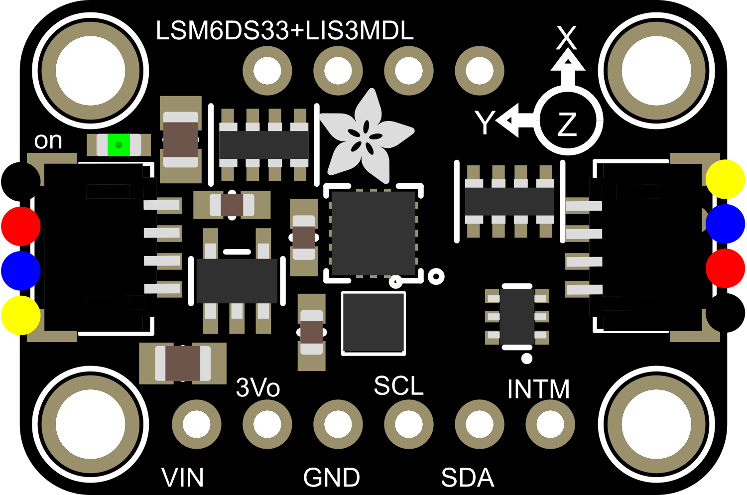
The Adafruit LIS3MDL + LSM6DS33 is a comprehensive 9 Degrees of Freedom (DoF) Inertial Measurement Unit (IMU) that integrates a 3-axis accelerometer, 3-axis gyroscope, and 3-axis magnetometer. This module is designed for motion tracking and orientation sensing in a wide range of applications, including robotics, drones, gaming devices, and virtual reality systems. Its small form factor and low power consumption make it ideal for portable and battery-powered devices.
Explore Projects Built with Adafruit LIS3MDL + LSM6DS33 - 9 DoF IMU with Accel + Gyro + Mag
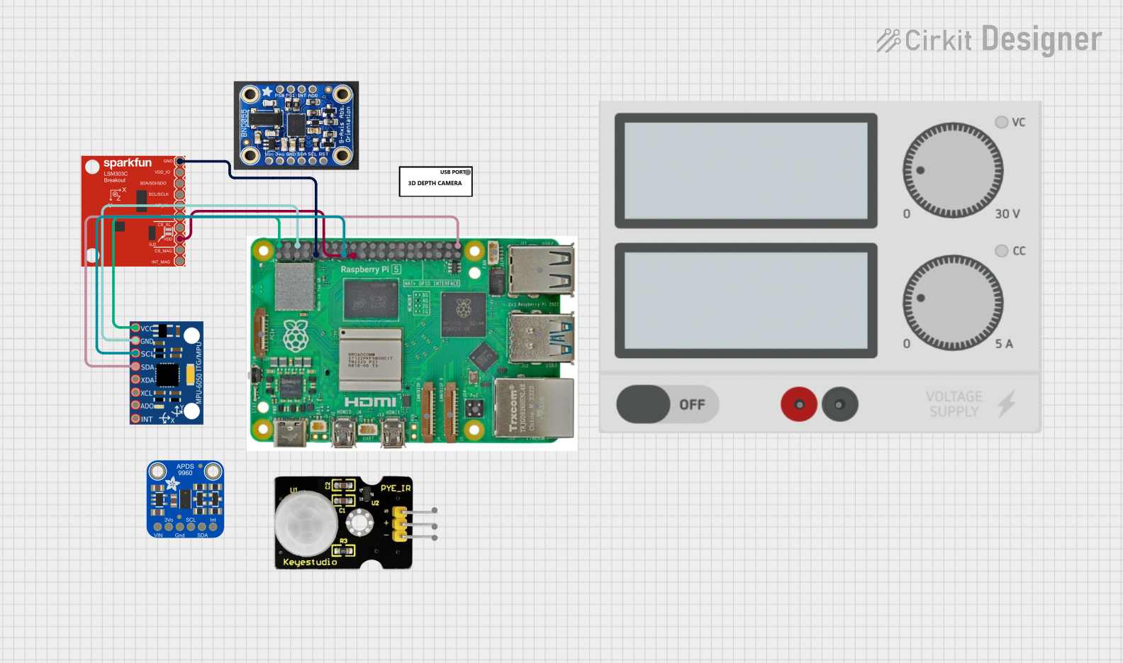
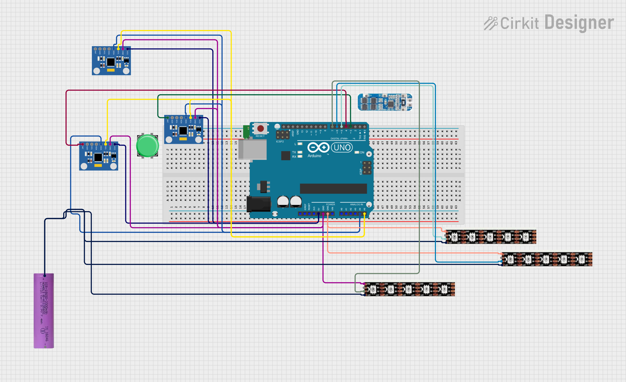

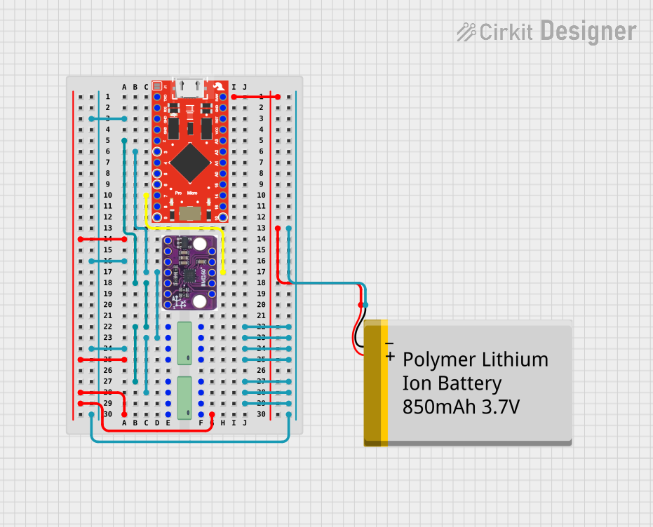
Explore Projects Built with Adafruit LIS3MDL + LSM6DS33 - 9 DoF IMU with Accel + Gyro + Mag
Technical Specifications
General Features
- 3-axis digital accelerometer with selectable full-scale range of ±2/±4/±8/±16 g
- 3-axis digital gyroscope with selectable full-scale range of ±125/±245/±500/±1000/±2000 dps
- 3-axis digital magnetometer with a full-scale range of ±4/±8/±12/±16 gauss
- I2C interface for communication with microcontrollers
- Supply voltage: 1.9V to 3.6V
- Operating temperature range: -40°C to +85°C
Pin Configuration and Descriptions
| Pin Number | Name | Description |
|---|---|---|
| 1 | VIN | Supply voltage (1.9V to 3.6V) |
| 2 | GND | Ground connection |
| 3 | SCL | I2C clock line |
| 4 | SDA | I2C data line |
| 5 | INT1 | Interrupt output for LSM6DS33 |
| 6 | INT2 | Interrupt output for LIS3MDL |
| 7 | ADDR | I2C address selection for LSM6DS33 |
| 8 | ID | Device identification pin |
Usage Instructions
Integration into a Circuit
- Connect VIN to a power supply within the specified voltage range.
- Connect GND to the ground of your power supply.
- Connect SCL and SDA to the I2C clock and data lines on your microcontroller, respectively.
- Optionally, connect INT1 and INT2 to interrupt-capable pins on your microcontroller if interrupt-driven operation is desired.
- If using multiple I2C devices, ensure that the ADDR pin is set correctly to avoid address conflicts.
Best Practices
- Use pull-up resistors on the I2C lines (SCL and SDA) as required by your microcontroller's I2C implementation.
- Place the IMU module away from magnetic fields and vibration sources to avoid interference and noise.
- Calibrate the magnetometer in the final installation environment to account for any magnetic distortions.
Example Code for Arduino UNO
#include <Wire.h>
#include <Adafruit_Sensor.h>
#include <Adafruit_LIS3MDL.h>
#include <Adafruit_LSM6DS33.h>

// Create sensor instances
Adafruit_LIS3MDL lis3mdl = Adafruit_LIS3MDL();
Adafruit_LSM6DS33 lsm6ds33 = Adafruit_LSM6DS33();

void setup() {
  Serial.begin(115200);
  // Initialize the LIS3MDL magnetometer
  if (!lis3mdl.begin_I2C()) {
    Serial.println("Failed to initialize LIS3MDL!");
    while (1);
  }
  // Initialize the LSM6DS33 accelerometer and gyroscope
  if (!lsm6ds33.begin_I2C()) {
    Serial.println("Failed to initialize LSM6DS33!");
    while (1);
  }
}

void loop() {
  // Read and print accelerometer and gyroscope data
  lsm6ds33.read();
  Serial.print("Accel X: "); Serial.print(lsm6ds33.acceleration.x);
  Serial.print(" Y: "); Serial.print(lsm6ds33.acceleration.y);
  Serial.print(" Z: "); Serial.println(lsm6ds33.acceleration.z);
  Serial.print("Gyro X: "); Serial.print(lsm6ds33.gyro.x);
  Serial.print(" Y: "); Serial.print(lsm6ds33.gyro.y);
  Serial.print(" Z: "); Serial.println(lsm6ds33.gyro.z);

  // Read and print magnetometer data
  lis3mdl.read();
  Serial.print("Mag X: "); Serial.print(lis3mdl.magnetic.x);
  Serial.print(" Y: "); Serial.print(lis3mdl.magnetic.y);
  Serial.print(" Z: "); Serial.println(lis3mdl.magnetic.z);

  delay(1000); // Delay for readability
}
Troubleshooting and FAQs
Common Issues
- I2C Communication Failure: Ensure that the VIN and GND connections are secure and within the specified voltage range. Check the pull-up resistors on the I2C lines.
- Inaccurate Readings: Perform sensor calibration, especially for the magnetometer, and ensure that the IMU is placed away from magnetic fields and vibration sources.
- Interrupts Not Working: Verify that the INT1 and INT2 pins are connected to interrupt-capable pins on your microcontroller and that the interrupt settings in your code are correct.
FAQs
Q: Can I use this IMU module with a 5V microcontroller? A: While the IMU module operates at 1.9V to 3.6V, many 5V microcontrollers have I2C lines that are 3.3V tolerant. Use a logic level converter if necessary.
Q: How do I change the I2C address of the LSM6DS33? A: The I2C address can be changed by connecting the ADDR pin to either GND or VIN, depending on the desired address.
Q: What is the default I2C address for the sensors? A: The default I2C address for the LIS3MDL is 0x1E and for the LSM6DS33 is 0x6B (ADDR pin to GND) or 0x6A (ADDR pin to VIN).
Q: How do I calibrate the magnetometer? A: Calibration typically involves rotating the sensor in various orientations and using software to record and compensate for any biases or distortions. Refer to the Adafruit guide for detailed calibration instructions.
For further assistance, consult the Adafruit support forums or the detailed datasheets for the LIS3MDL and LSM6DS33 sensors.