
How to Use Adafruit DC+Stepper FeatherWing: Examples, Pinouts, and Specs
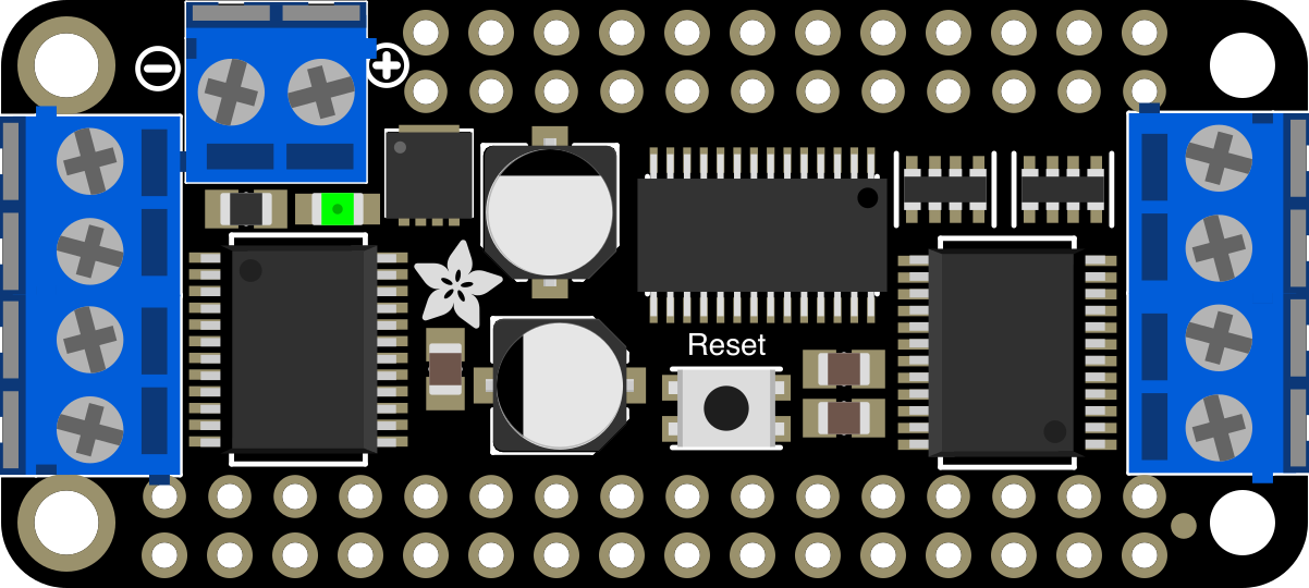
 Design with Adafruit DC+Stepper FeatherWing in Cirkit Designer
Introduction
The Adafruit DC+Stepper FeatherWing (Part ID: 2927) is a versatile add-on board designed for Feather microcontrollers. It enables users to control both DC motors and stepper motors with ease, thanks to its built-in motor drivers and straightforward connections for power and control. This FeatherWing is ideal for robotics, automation, and motion control projects, offering a compact and efficient solution for motor control.
Explore Projects Built with Adafruit DC+Stepper FeatherWing
 Open Project in Cirkit Designer
 Open Project in Cirkit Designer
 Open Project in Cirkit Designer
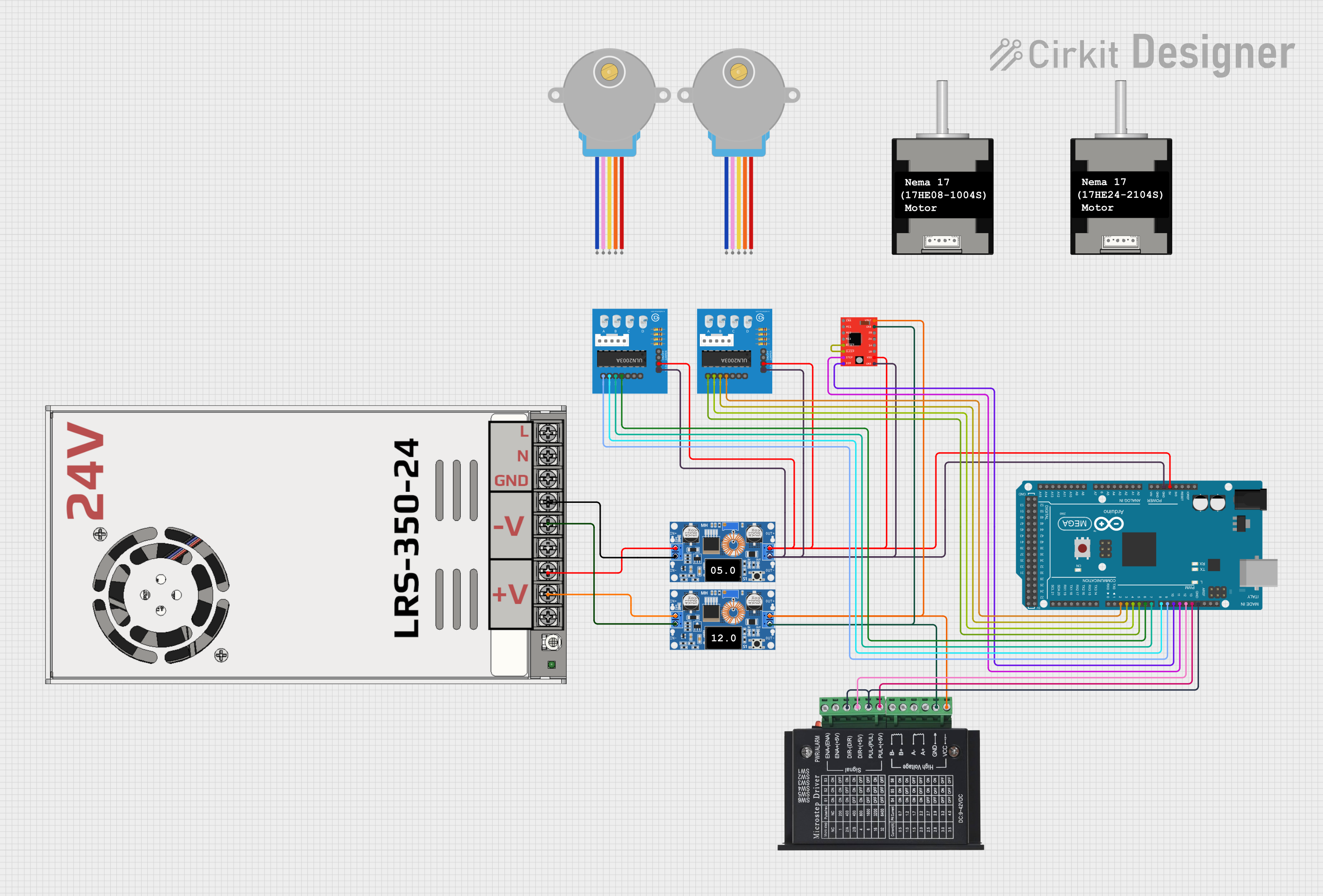 Open Project in Cirkit Designer
Explore Projects Built with Adafruit DC+Stepper FeatherWing
Open Project in Cirkit DesignerOpen Project in Cirkit DesignerOpen Project in Cirkit DesignerOpen Project in Cirkit DesignerCommon Applications and Use Cases
- Robotics projects requiring precise motor control
- Automated systems such as conveyor belts or robotic arms
- DIY CNC machines and 3D printers
- Educational projects for learning motor control
- Prototyping motion-based systems
Technical Specifications
Key Technical Details
- Motor Driver IC: TB6612 MOSFET driver
- Motor Control: Supports up to 4 DC motors or 2 stepper motors
- Voltage Range: 4.5V to 13.5V (motor power supply)
- Current Rating: 1.2A per channel (continuous), 3.2A peak
- Communication Protocol: I2C (default address: 0x60, configurable)
- Dimensions: 51mm x 23mm x 8mm (excluding headers)
- Weight: 5.5g
Pin Configuration and Descriptions
The Adafruit DC+Stepper FeatherWing connects directly to Feather microcontrollers via its headers. Below is a description of its key pins and connectors:
FeatherWing Header Pins
| Pin | Description |
|---|---|
| VIN | Power input for motors (4.5V to 13.5V). |
| GND | Ground connection. |
| SDA | I2C data line. |
| SCL | I2C clock line. |
Motor Terminal Blocks
| Terminal | Description |
|---|---|
| M1+ / M1- | Terminals for DC motor 1 or stepper motor coil A. |
| M2+ / M2- | Terminals for DC motor 2 or stepper motor coil B. |
| M3+ / M3- | Terminals for DC motor 3 (if using DC motors only). |
| M4+ / M4- | Terminals for DC motor 4 (if using DC motors only). |
Additional Features
- Address Jumpers: Solderable pads to configure I2C address.
- Power Jumper: Option to connect Feather's VIN to motor power.
Usage Instructions
How to Use the Component in a Circuit
- Connect the FeatherWing to a Feather Board: Align the FeatherWing's headers with the Feather microcontroller and press them together.
- Power the Motors: Connect an external power supply (4.5V to 13.5V) to the VIN and GND terminals. Ensure the power supply matches the voltage and current requirements of your motors.
- Connect Motors: Attach DC motors or stepper motors to the terminal blocks (M1+/M1-, M2+/M2-, etc.).
- Configure I2C Address (if needed): If using multiple FeatherWings, solder the address jumpers to set unique I2C addresses.
- Install Required Libraries: Download and install the Adafruit Motor Shield library for Arduino from the Arduino Library Manager.
- Write and Upload Code: Use the provided library functions to control the motors.
Important Considerations and Best Practices
- Power Supply: Use a power supply that can handle the combined current draw of all connected motors.
- Heat Dissipation: The motor driver ICs may get warm during operation. Ensure adequate ventilation.
- I2C Address Conflicts: If using multiple I2C devices, ensure each has a unique address.
- Motor Type: Verify the motor type (DC or stepper) and connect it to the appropriate terminals.
Example Code for Arduino UNO
Below is an example of how to control a DC motor using the Adafruit DC+Stepper FeatherWing:
#include <Wire.h>
#include <Adafruit_MotorShield.h>

// Create the motor shield object
Adafruit_MotorShield AFMS = Adafruit_MotorShield();

// Select the motor port (M1, M2, M3, or M4)
Adafruit_DCMotor *myMotor = AFMS.getMotor(1);

void setup() {
  Serial.begin(9600); // Initialize serial communication
  Serial.println("Adafruit DC+Stepper FeatherWing Test");

  AFMS.begin(); // Initialize the motor shield

  myMotor->setSpeed(150); // Set motor speed (0-255)
  myMotor->run(FORWARD);  // Set motor direction to forward
}

void loop() {
  myMotor->run(FORWARD);  // Run motor forward
  delay(2000);            // Wait for 2 seconds

  myMotor->run(BACKWARD); // Run motor backward
  delay(2000);            // Wait for 2 seconds

  myMotor->run(RELEASE);  // Stop the motor
  delay(1000);            // Wait for 1 second
}
Troubleshooting and FAQs
Common Issues and Solutions
Motors Not Running
- Cause: Insufficient power supply.
- Solution: Verify that the VIN terminal is receiving the correct voltage and current.
I2C Communication Failure
- Cause: Address conflict or incorrect wiring.
- Solution: Check the I2C address and ensure SDA/SCL lines are properly connected.
Motor Driver Overheating
- Cause: Excessive current draw from motors.
- Solution: Use motors within the current rating of the driver (1.2A continuous).
Stepper Motor Not Moving Smoothly
- Cause: Incorrect wiring of motor coils.
- Solution: Verify the coil connections and ensure they are correctly paired.
FAQs
Can I use this FeatherWing with non-Adafruit Feather boards?
- Yes, as long as the board supports I2C communication and has compatible headers.
What is the maximum number of FeatherWings I can stack?
- Up to 32 FeatherWings can be stacked by configuring unique I2C addresses.
Can I control both DC and stepper motors simultaneously?
- Yes, you can mix and match DC and stepper motors, as long as the total number of motors does not exceed the available channels.
Is it possible to power the Feather board from the FeatherWing?
- Yes, by soldering the power jumper, you can connect the Feather's VIN to the motor power supply.