How to Use MTF-02: Examples, Pinouts, and Specs

 Design with MTF-02 in Cirkit Designer
Introduction
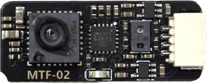
The MTF-02 is a versatile multi-functional test fixture designed for testing and validating electronic circuits and components. It serves as a critical tool for engineers, hobbyists, and technicians by providing multiple connection points and interfaces for measuring electrical parameters such as voltage, current, resistance, and more. The MTF-02 simplifies prototyping, troubleshooting, and circuit analysis, making it an indispensable component in any electronics lab.
Explore Projects Built with MTF-02

 Open Project in Cirkit Designer
 Open Project in Cirkit Designer
 Open Project in Cirkit Designer
 Open Project in Cirkit Designer
Explore Projects Built with MTF-02

 Open Project in Cirkit Designer
 Open Project in Cirkit Designer
 Open Project in Cirkit Designer
 Open Project in Cirkit Designer
Common Applications and Use Cases
- Prototyping and testing new circuit designs
- Troubleshooting faulty circuits and components
- Measuring electrical parameters during development
- Educational purposes for teaching circuit analysis
- Validation of electronic components in production environments
Technical Specifications
Key Technical Details
| Parameter | Value |
|---|---|
| Manufacturer Part ID | MTF-02 |
| Operating Voltage Range | 0 - 30V DC |
| Maximum Current Handling | 5A |
| Measurement Accuracy | ±0.5% |
| Supported Measurements | Voltage, Current, Resistance |
| Interface Type | Banana jacks, screw terminals |
| Dimensions | 120mm x 80mm x 30mm |
| Weight | 150g |
Pin Configuration and Descriptions
The MTF-02 features multiple connection points for interfacing with circuits and test equipment. Below is a description of the key interfaces:
| Pin/Port Name | Type | Description |
|---|---|---|
| V+ (Banana Jack) | Input/Output | Positive voltage input/output for connecting to the circuit under test. |
| V- (Banana Jack) | Input/Output | Negative voltage input/output for connecting to the circuit under test. |
| GND | Ground | Common ground connection for the circuit under test. |
| Current Test Port | Input/Output | Dedicated port for measuring current in the circuit. |
| Resistance Test | Input/Output | Port for measuring resistance of components or circuits. |
| Screw Terminals | Input/Output | Additional connection points for secure wiring to the circuit under test. |
| USB Interface | Communication | Optional interface for connecting to a PC for data logging (if supported). |
Usage Instructions
How to Use the MTF-02 in a Circuit
Powering the Test Fixture:
- Ensure the power supply connected to the MTF-02 is within the operating voltage range (0-30V DC).
- Connect the positive terminal of the power supply to the
V+port and the negative terminal to theV-port.
Connecting the Circuit Under Test:
- Use the banana jacks or screw terminals to connect the circuit under test to the MTF-02.
- Ensure proper polarity when connecting voltage or current sources.
Measuring Voltage:
- Connect the voltage source to the
V+andV-ports. - Use a multimeter or the MTF-02's built-in measurement interface (if available) to read the voltage.
- Connect the voltage source to the
Measuring Current:
- Insert the MTF-02 in series with the circuit under test using the
Current Test Port. - Ensure the current does not exceed the maximum rating of 5A.
- Insert the MTF-02 in series with the circuit under test using the
Measuring Resistance:
- Connect the component or circuit to the
Resistance Testport. - Use the MTF-02's interface or an external multimeter to measure resistance.
- Connect the component or circuit to the
Data Logging (Optional):
- If the MTF-02 includes a USB interface, connect it to a PC using a USB cable.
- Use compatible software to log and analyze measurement data.
Important Considerations and Best Practices
- Always verify the polarity of connections to avoid damage to the MTF-02 or the circuit under test.
- Do not exceed the maximum current rating of 5A to prevent overheating or damage.
- Use proper insulation and secure connections to avoid short circuits.
- If using the USB interface, ensure the software drivers are correctly installed on your PC.
- Disconnect power before making any changes to the circuit connections.
Example: Using the MTF-02 with an Arduino UNO
The MTF-02 can be used to measure the voltage and current of an Arduino UNO circuit. Below is an example of how to measure the current drawn by an LED connected to an Arduino UNO:
Circuit Setup
- Connect the
V+andV-ports of the MTF-02 to the Arduino's 5V and GND pins, respectively. - Insert the MTF-02's
Current Test Portin series with the LED and its current-limiting resistor.
Arduino Code
// Example Arduino code to blink an LED
// This code is used to test the current drawn by the LED

const int ledPin = 13; // Pin connected to the LED

void setup() {
  pinMode(ledPin, OUTPUT); // Set the LED pin as an output
}

void loop() {
  digitalWrite(ledPin, HIGH); // Turn the LED on
  delay(1000);                // Wait for 1 second
  digitalWrite(ledPin, LOW);  // Turn the LED off
  delay(1000);                // Wait for 1 second
}
Troubleshooting and FAQs
Common Issues and Solutions
No Power to the MTF-02:
- Cause: Incorrect or loose power supply connections.
- Solution: Verify that the power supply is properly connected to the
V+andV-ports and is within the operating voltage range.
Inaccurate Measurements:
- Cause: Poor connections or exceeding the measurement range.
- Solution: Ensure all connections are secure and within the specified voltage/current limits.
Overheating:
- Cause: Exceeding the maximum current rating of 5A.
- Solution: Reduce the current load and allow the MTF-02 to cool before resuming use.
USB Interface Not Recognized:
- Cause: Missing or incorrect drivers.
- Solution: Install the correct drivers for the MTF-02's USB interface and restart the PC.
FAQs
Q: Can the MTF-02 measure AC voltage or current?
A: No, the MTF-02 is designed for DC measurements only.Q: Is the MTF-02 compatible with all multimeters?
A: Yes, the MTF-02 can be used with any standard multimeter for voltage, current, and resistance measurements.Q: Can I use the MTF-02 with high-power circuits?
A: The MTF-02 is rated for a maximum current of 5A. For higher power circuits, use appropriate test equipment.Q: Does the MTF-02 require calibration?
A: The MTF-02 is factory-calibrated, but periodic calibration is recommended for precise measurements.