How to Use Esp32: Examples, Pinouts, and Specs
Introduction
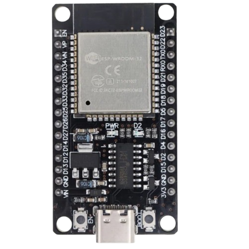
The ESP32, manufactured by ESP, is a low-cost, low-power system on a chip (SoC) designed for a wide range of applications. It integrates Wi-Fi and Bluetooth capabilities, making it an ideal choice for Internet of Things (IoT) projects, smart devices, and embedded systems. The ESP32 is highly versatile, offering dual-core processing, a rich set of peripherals, and extensive GPIO options.
Explore Projects Built with Esp32


Explore Projects Built with Esp32
Common Applications and Use Cases
- IoT devices (e.g., smart home systems, sensors, and actuators)
- Wearable electronics
- Wireless communication systems
- Robotics and automation
- Data logging and remote monitoring
- Prototyping and educational projects
Technical Specifications
The ESP32 is a feature-rich SoC with the following key specifications:
| Parameter | Value |
|---|---|
| Manufacturer | ESP |
| Part ID | ESP32 |
| Processor | Dual-core Xtensa® 32-bit LX6 microprocessor |
| Clock Speed | Up to 240 MHz |
| Flash Memory | 4 MB (varies by module) |
| SRAM | 520 KB |
| Wireless Connectivity | Wi-Fi 802.11 b/g/n, Bluetooth v4.2 + BLE |
| Operating Voltage | 3.0V to 3.6V |
| GPIO Pins | 34 (multiplexed with other functions) |
| ADC Channels | 18 (12-bit resolution) |
| DAC Channels | 2 |
| Communication Interfaces | UART, SPI, I2C, I2S, CAN, PWM |
| Power Consumption | Ultra-low power (supports deep sleep mode with <10 µA current draw) |
| Operating Temperature | -40°C to +125°C |
Pin Configuration and Descriptions
The ESP32 has a flexible pinout, with GPIO pins that can be configured for various functions. Below is a table summarizing the key pins:
| Pin Name | Function | Description |
|---|---|---|
| GPIO0 | Input/Output, Boot Mode Select | Used for boot mode selection during startup. |
| GPIO2 | Input/Output, ADC, PWM | General-purpose pin with ADC and PWM capabilities. |
| GPIO12 | Input/Output, ADC, Touch Sensor | Can be used as an ADC input or capacitive touch sensor. |
| GPIO13 | Input/Output, ADC, Touch Sensor | Similar to GPIO12, supports ADC and touch sensing. |
| GPIO15 | Input/Output, ADC, PWM | General-purpose pin with ADC and PWM capabilities. |
| EN | Enable Pin | Active-high pin to enable or reset the chip. |
| 3V3 | Power Supply | Provides 3.3V power output. |
| GND | Ground | Ground connection. |
Note: The ESP32 has many more GPIO pins and functions. Refer to the official datasheet for a complete pinout.
Usage Instructions
How to Use the ESP32 in a Circuit
Powering the ESP32:
- Connect the 3.3V pin to a regulated 3.3V power source.
- Ensure the GND pin is connected to the ground of the circuit.
- Avoid supplying more than 3.6V to prevent damage to the chip.
Programming the ESP32:
- Use a USB-to-serial adapter or a development board with a built-in USB interface.
- Install the ESP32 board package in the Arduino IDE or use the ESP-IDF framework for advanced development.
- Connect the ESP32 to your computer via USB and select the appropriate COM port in the IDE.
Connecting Peripherals:
- Use GPIO pins for interfacing with sensors, actuators, and other devices.
- Configure the pins in your code to match the required functionality (e.g., input, output, ADC, PWM).
Important Considerations and Best Practices
- Voltage Levels: The ESP32 operates at 3.3V logic levels. Use level shifters if interfacing with 5V devices.
- Power Supply: Ensure a stable power supply to avoid unexpected resets or malfunctions.
- Deep Sleep Mode: Use deep sleep mode to minimize power consumption in battery-powered applications.
- Pin Multiplexing: Be aware that many GPIO pins are multiplexed with other functions. Check the datasheet to avoid conflicts.
Example Code for Arduino UNO Integration
Below is an example of using the ESP32 to read a sensor value and send it over Wi-Fi:
#include <WiFi.h> // Include the Wi-Fi library

// Replace with your network credentials
const char* ssid = "Your_SSID";
const char* password = "Your_PASSWORD";

void setup() {
  Serial.begin(115200); // Initialize serial communication
  WiFi.begin(ssid, password); // Connect to Wi-Fi

  // Wait for connection
  while (WiFi.status() != WL_CONNECTED) {
    delay(1000);
    Serial.println("Connecting to Wi-Fi...");
  }
  Serial.println("Connected to Wi-Fi!");
}

void loop() {
  // Example: Read a sensor value (e.g., analog pin A0)
  int sensorValue = analogRead(34); // GPIO34 is an ADC pin
  Serial.print("Sensor Value: ");
  Serial.println(sensorValue);

  delay(1000); // Wait for 1 second before the next reading
}
Note: Replace
Your_SSIDandYour_PASSWORDwith your Wi-Fi network credentials.
Troubleshooting and FAQs
Common Issues and Solutions
ESP32 Not Connecting to Wi-Fi:
- Ensure the SSID and password are correct.
- Check if the Wi-Fi network is within range.
- Verify that the router supports 2.4 GHz, as the ESP32 does not support 5 GHz.
Frequent Resets or Instability:
- Check the power supply for stability and sufficient current (at least 500 mA).
- Avoid using GPIO pins that are connected to bootstrapping functions during startup.
Upload Errors in Arduino IDE:
- Ensure the correct board and COM port are selected in the IDE.
- Press and hold the "BOOT" button on the ESP32 board while uploading the code.
GPIO Pin Not Working:
- Verify that the pin is not being used for another function (e.g., ADC, touch sensor).
- Check for short circuits or incorrect wiring.
FAQs
Q: Can the ESP32 be powered directly from a USB port?
A: Yes, if you are using an ESP32 development board with a built-in USB interface, it can be powered directly via USB.
Q: How do I update the firmware on the ESP32?
A: Use the ESP-IDF or Arduino IDE to upload new firmware. Ensure the correct boot mode is selected during the process.
Q: Can the ESP32 connect to both Wi-Fi and Bluetooth simultaneously?
A: Yes, the ESP32 supports simultaneous Wi-Fi and Bluetooth operation, but performance may vary depending on the application.
Q: What is the maximum range of the ESP32's Wi-Fi?
A: The range depends on environmental factors but typically extends up to 100 meters in open spaces.
For more detailed information, refer to the official ESP32 datasheet and technical reference manual.