How to Use USB-C Terminal Adapter: Examples, Pinouts, and Specs
Introduction
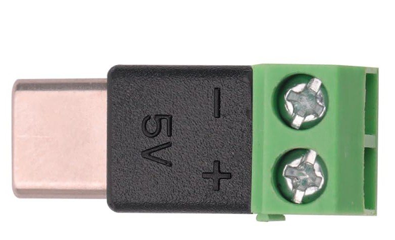
The USB-C Terminal Adapter is a versatile electronic component designed to bridge USB-C devices with other interfaces. It supports data transfer, power delivery, and video output, all through a single, reversible USB-C connector. This adapter simplifies connectivity by enabling seamless integration with a variety of devices, including laptops, smartphones, and peripherals.
Explore Projects Built with USB-C Terminal Adapter


Explore Projects Built with USB-C Terminal Adapter
Common Applications and Use Cases
- Data Transfer: High-speed data communication between USB-C devices and legacy USB or other interfaces.
- Power Delivery: Charging devices with support for USB Power Delivery (USB-PD) standards.
- Video Output: Connecting USB-C devices to external displays via HDMI, DisplayPort, or VGA.
- Prototyping: Used in electronics projects to interface USB-C with microcontrollers or other hardware.
Technical Specifications
The USB-C Terminal Adapter comes with the following key specifications:
| Specification | Details |
|---|---|
| Connector Type | USB Type-C (Reversible) |
| Voltage Range | 5V to 20V (Supports USB Power Delivery) |
| Maximum Current | Up to 5A (Depending on cable and power source) |
| Data Transfer Rate | Up to 10 Gbps (USB 3.1 Gen 2, depending on the adapter model) |
| Video Output Standards | HDMI, DisplayPort, or VGA (Varies by adapter type) |
| Operating Temperature | -20°C to 60°C |
| Dimensions | Typically compact, varies by manufacturer |
Pin Configuration and Descriptions
The USB-C connector has 24 pins, but the terminal adapter typically exposes only the most commonly used pins for prototyping or interfacing. Below is a simplified pinout:
| Pin Name | Description |
|---|---|
| VBUS | Power supply pin (5V to 20V, depending on USB-PD negotiation) |
| GND | Ground connection |
| D+ | USB 2.0 differential data line (positive) |
| D- | USB 2.0 differential data line (negative) |
| TX+ | USB 3.x SuperSpeed differential pair (positive, for data transmission) |
| TX- | USB 3.x SuperSpeed differential pair (negative, for data transmission) |
| RX+ | USB 3.x SuperSpeed differential pair (positive, for data reception) |
| RX- | USB 3.x SuperSpeed differential pair (negative, for data reception) |
| CC1, CC2 | Configuration Channel pins (used for cable orientation and power negotiation) |
| SBU1, SBU2 | Sideband use pins (used for alternate modes like video output) |
Note: Not all pins may be exposed or utilized, depending on the specific terminal adapter model.
Usage Instructions
How to Use the USB-C Terminal Adapter in a Circuit
- Power Supply: Connect the VBUS and GND pins to provide power to your circuit. Ensure the voltage and current ratings are within the supported range.
- Data Communication: Use the D+ and D- pins for USB 2.0 communication or the TX/RX pairs for USB 3.x communication.
- Video Output: If your adapter supports video output, connect the SBU pins and appropriate alternate mode pins to the display interface.
- Configuration: Use the CC pins for USB-C cable orientation detection and power delivery negotiation.
Important Considerations and Best Practices
- Voltage and Current Ratings: Always verify the voltage and current requirements of your connected devices to avoid damage.
- Cable Quality: Use high-quality USB-C cables to ensure reliable data transfer and power delivery.
- Alternate Modes: For video output, ensure your device supports the required alternate mode (e.g., DisplayPort Alt Mode).
- Prototyping: When using the adapter for prototyping, double-check pin connections to avoid short circuits.
Example: Connecting to an Arduino UNO
While the Arduino UNO does not natively support USB-C, you can use the USB-C Terminal Adapter to interface with it for power or data communication. Below is an example of using the adapter to power the Arduino UNO:
// Example: Powering Arduino UNO via USB-C Terminal Adapter
// Connect the VBUS pin of the USB-C adapter to the 5V pin on the Arduino UNO.
// Connect the GND pin of the USB-C adapter to the GND pin on the Arduino UNO.

void setup() {
  // No specific setup required for power-only connection
}

void loop() {
  // Your Arduino code here
}
Tip: For data communication, you may need a USB-to-serial converter if your USB-C adapter does not natively support UART.
Troubleshooting and FAQs
Common Issues and Solutions
No Power Output:
- Cause: Incorrect power source or cable.
- Solution: Verify the power source and ensure the cable supports power delivery.
Data Transfer Fails:
- Cause: Incorrect pin connections or incompatible devices.
- Solution: Double-check the pin connections and ensure both devices support the same USB standard.
Video Output Not Working:
- Cause: Device does not support the required alternate mode.
- Solution: Confirm that your device supports video output (e.g., DisplayPort Alt Mode).
Overheating:
- Cause: Excessive current draw or poor ventilation.
- Solution: Ensure the connected devices do not exceed the adapter's current rating and provide adequate cooling.
FAQs
Q: Can I use the USB-C Terminal Adapter with a USB 2.0 device?
A: Yes, the adapter is backward compatible with USB 2.0, but data transfer rates will be limited to USB 2.0 speeds.Q: Does the adapter support fast charging?
A: Yes, if the adapter and connected devices support USB Power Delivery (USB-PD).Q: Can I use this adapter for audio output?
A: Some USB-C adapters support audio output, but this depends on the specific model and device compatibility.Q: How do I know if my device supports video output?
A: Check your device's specifications for support of DisplayPort Alt Mode or HDMI over USB-C.
By following this documentation, you can effectively utilize the USB-C Terminal Adapter in your projects and troubleshoot common issues with ease.