
How to Use LTC3588: Examples, Pinouts, and Specs

 Design with LTC3588 in Cirkit Designer
Introduction
The LTC3588 is a high-efficiency energy harvesting integrated circuit (IC) designed to convert small amounts of energy from sources such as thermoelectric generators (TEGs), piezoelectric devices, or solar cells into usable power. It is particularly suited for low-power applications, where energy harvesting is critical to extend battery life or eliminate the need for batteries altogether. The LTC3588 features a built-in boost converter, which steps up the input voltage to levels suitable for powering microcontrollers, sensors, and other low-power electronic devices.
Explore Projects Built with LTC3588
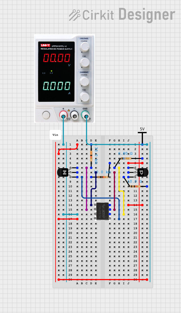 Open Project in Cirkit Designer
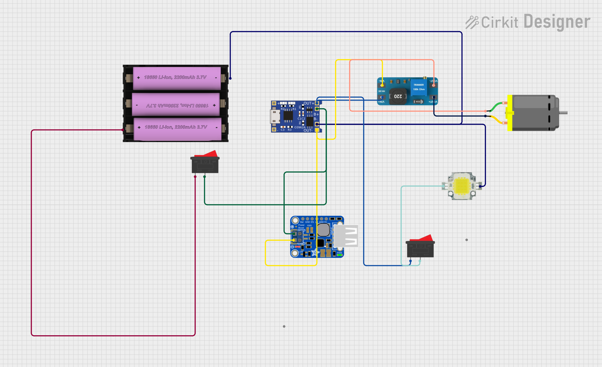 Open Project in Cirkit Designer
 Open Project in Cirkit Designer
 Open Project in Cirkit Designer
Explore Projects Built with LTC3588
Open Project in Cirkit DesignerOpen Project in Cirkit DesignerOpen Project in Cirkit DesignerOpen Project in Cirkit DesignerCommon Applications
- Wireless sensor networks
- Industrial monitoring systems
- Wearable electronics
- IoT (Internet of Things) devices
- Energy harvesting from piezoelectric or thermoelectric sources
Technical Specifications
Key Technical Details
- Input Voltage Range: 2.7V to 20V
- Output Voltage Options: 1.8V, 2.5V, 3.3V, or 3.6V (selectable via pins)
- Quiescent Current: 950nA (typical)
- Maximum Output Current: 100mA (depending on input power source)
- Integrated Rectifier: For AC energy sources like piezoelectric devices
- Efficiency: Up to 90% (depending on input/output conditions)
- Operating Temperature Range: -40°C to 85°C
- Package: 10-lead DFN (3mm × 3mm)
Pin Configuration and Descriptions
The LTC3588 is available in a 10-lead DFN package. Below is the pin configuration and description:
| Pin Number | Pin Name | Description |
|---|---|---|
| 1 | VIN | Input voltage from the energy source (2.7V to 20V). |
| 2 | GND | Ground connection. |
| 3 | VSTORE | Storage capacitor connection for harvested energy. |
| 4 | VOUT | Regulated output voltage (1.8V, 2.5V, 3.3V, or 3.6V). |
| 5 | VSEL0 | Output voltage selection pin (used with VSEL1). |
| 6 | VSEL1 | Output voltage selection pin (used with VSEL0). |
| 7 | EN | Enable pin for the regulator (active high). |
| 8 | PGOOD | Power-good indicator (high when output voltage is within regulation). |
| 9 | AC1 | Input for AC energy sources (e.g., piezoelectric devices). |
| 10 | AC2 | Input for AC energy sources (e.g., piezoelectric devices). |
Output Voltage Selection Table
The output voltage is configured using the VSEL0 and VSEL1 pins as shown below:
| VSEL1 | VSEL0 | Output Voltage |
|---|---|---|
| 0 | 0 | 1.8V |
| 0 | 1 | 2.5V |
| 1 | 0 | 3.3V |
| 1 | 1 | 3.6V |
Usage Instructions
Using the LTC3588 in a Circuit
Connect the Energy Source:
- For DC sources (e.g., solar cells), connect the positive terminal to the VIN pin and the negative terminal to GND.
- For AC sources (e.g., piezoelectric devices), connect the source to the AC1 and AC2 pins. The LTC3588 has an integrated rectifier to convert AC to DC.
Select the Output Voltage:
- Use the VSEL0 and VSEL1 pins to configure the desired output voltage as per the table above.
- For example, to set the output voltage to 3.3V, set VSEL1 = 1 and VSEL0 = 0.
Connect the Storage Capacitor:
- Attach a capacitor (e.g., 10µF to 100µF) to the VSTORE pin to store harvested energy. This capacitor smooths out fluctuations in the input power.
Enable the Regulator:
- Pull the EN pin high to enable the output voltage regulation. If the EN pin is low, the output will be disabled.
Connect the Load:
- Attach your load (e.g., microcontroller, sensor) to the VOUT pin. Ensure the load does not exceed the maximum output current of the LTC3588.
Important Considerations
- Input Source Impedance: Ensure the energy source can provide sufficient power for the desired output voltage and load.
- Storage Capacitor Selection: Use a low-ESR capacitor to improve efficiency and stability.
- Thermal Management: Although the LTC3588 is highly efficient, ensure adequate thermal dissipation if operating near maximum power levels.
- Startup Behavior: The LTC3588 requires a minimum input voltage to start up. Ensure your energy source can provide at least 2.7V.
Example: Connecting the LTC3588 to an Arduino UNO
The LTC3588 can be used to power an Arduino UNO in low-power applications. Below is an example circuit and Arduino code to read a sensor value:
Circuit Connections
- Connect a solar cell to the VIN pin and GND.
- Set VSEL1 = 1 and VSEL0 = 0 to configure the output voltage to 3.3V.
- Connect the VOUT pin to the Arduino's 3.3V input pin.
- Connect the GND pin of the LTC3588 to the Arduino's GND.
Arduino Code
// Example code to read a sensor value and print it to the Serial Monitor
// Ensure the LTC3588 is providing sufficient power to the Arduino UNO.

const int sensorPin = A0; // Analog pin connected to the sensor
int sensorValue = 0;      // Variable to store the sensor reading

void setup() {
  Serial.begin(9600); // Initialize serial communication at 9600 baud
}

void loop() {
  sensorValue = analogRead(sensorPin); // Read the sensor value
  Serial.print("Sensor Value: ");
  Serial.println(sensorValue); // Print the sensor value to the Serial Monitor
  delay(1000); // Wait for 1 second before reading again
}
Troubleshooting and FAQs
Common Issues and Solutions
No Output Voltage:
- Ensure the EN pin is pulled high to enable the regulator.
- Verify that the input voltage is within the specified range (2.7V to 20V).
- Check the connections to the energy source and ensure it is providing sufficient power.
Output Voltage is Incorrect:
- Double-check the VSEL0 and VSEL1 pin configurations.
- Ensure the load does not exceed the maximum output current.
Device Overheating:
- Verify that the input power source is not exceeding the maximum input voltage (20V).
- Ensure proper thermal dissipation, especially in high-power applications.
Startup Issues:
- Ensure the energy source can provide at least 2.7V for startup.
- Use a larger storage capacitor on the VSTORE pin to help with startup transients.
FAQs
Can the LTC3588 work with piezoelectric energy sources? Yes, the LTC3588 has an integrated rectifier specifically designed for AC sources like piezoelectric devices.
What is the maximum output current of the LTC3588? The maximum output current depends on the input power source but is typically up to 100mA.
Can I use the LTC3588 to power a 5V device? No, the LTC3588's maximum output voltage is 3.6V. You would need an additional step-up converter to achieve 5V.
What type of capacitor should I use on the VSTORE pin? Use a low-ESR capacitor with a value between 10µF and 100µF for optimal performance.