How to Use 8 Channel mosfet: Examples, Pinouts, and Specs
Introduction
The 8 Channel MOSFET is a versatile electronic component designed to control multiple channels of current simultaneously. It is a type of transistor that operates as an efficient switch or amplifier, making it ideal for a wide range of applications. This component is particularly useful in scenarios requiring high-speed switching, low power loss, and precise control of multiple loads.
Explore Projects Built with 8 Channel mosfet
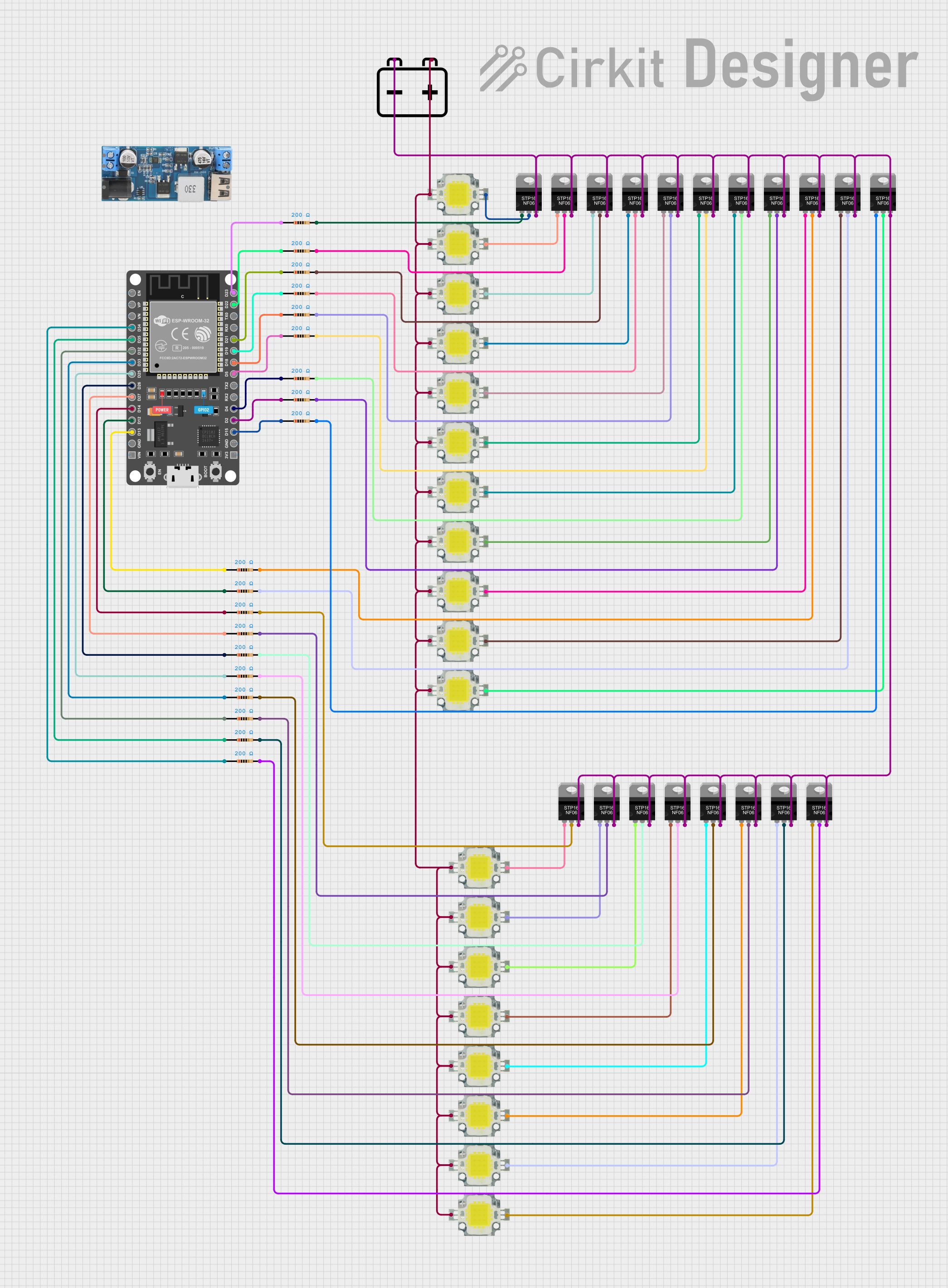
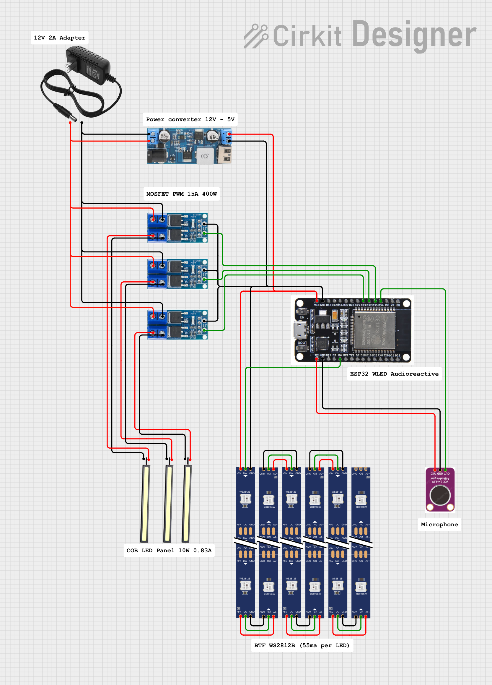
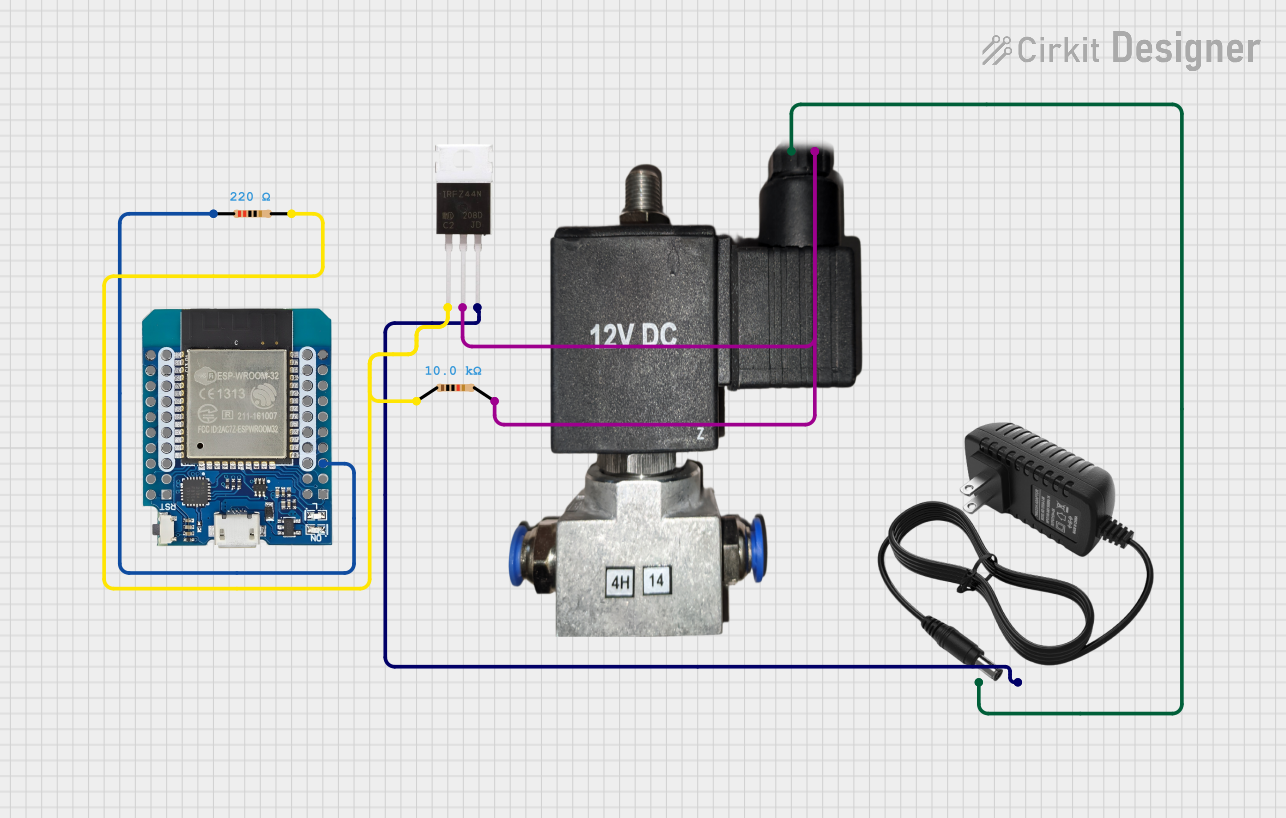

Explore Projects Built with 8 Channel mosfet
Common Applications and Use Cases
- Motor control for robotics and industrial automation
- LED strip and lighting control
- Power management in embedded systems
- Signal processing in audio and communication devices
- Driving solenoids, relays, and other inductive loads
Technical Specifications
Below are the key technical details for the 8 Channel MOSFET with manufacturer part ID: 3.3v.
General Specifications
- Number of Channels: 8
- Operating Voltage: 3.3V to 20V (logic level compatible)
- Maximum Drain Current (per channel): 10A
- Maximum Power Dissipation: 30W (with proper heat sinking)
- Gate Threshold Voltage: 2V to 4V
- On-Resistance (RDS(on)): < 0.1Ω
- Switching Speed: < 100ns
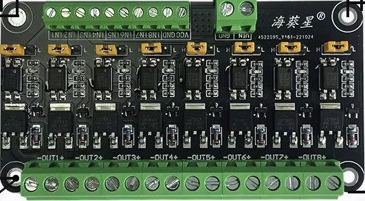
- Package Type: PCB module with screw terminals and pin headers
Pin Configuration and Descriptions
The 8 Channel MOSFET module typically includes the following pins:
| Pin Name | Description |
|---|---|
| GND | Ground connection for the module. |
| VCC | Power supply for the logic circuit (3.3V or 5V). |
| IN1 - IN8 | Control signal inputs for each MOSFET channel. Accepts 3.3V or 5V logic levels. |
| OUT1 - OUT8 | Output terminals for each MOSFET channel. Connect to the load. |
| VIN | Power input for the load (e.g., 12V or 24V). |
Usage Instructions
How to Use the Component in a Circuit
Power Connections:
- Connect the
VINpin to the power source for your load (e.g., 12V or 24V). - Connect the
GNDpin to the ground of your power source and the ground of your control circuit. - Provide 3.3V or 5V to the
VCCpin to power the logic circuit.
- Connect the
Control Signals:
- Use the
IN1toIN8pins to control each MOSFET channel. These pins accept logic-level signals (3.3V or 5V). - A HIGH signal (logic 1) on an input pin will turn on the corresponding MOSFET channel, allowing current to flow through the load connected to the respective
OUTpin.
- Use the
Load Connections:
- Connect the positive terminal of your load to the
VINpin. - Connect the negative terminal of your load to the desired
OUTpin (e.g.,OUT1for channel 1).
- Connect the positive terminal of your load to the
Important Considerations and Best Practices
- Heat Management: Ensure proper heat dissipation by using a heat sink or active cooling if the module operates near its maximum power rating.
- Inductive Loads: When driving inductive loads (e.g., motors or solenoids), use flyback diodes across the load terminals to protect the MOSFETs from voltage spikes.
- Logic Level Compatibility: Verify that the control signals are within the acceptable voltage range (3.3V or 5V).
- Current Limits: Do not exceed the maximum drain current (10A per channel) to avoid damaging the MOSFETs.
Example: Controlling an LED Strip with Arduino UNO
Below is an example of how to use the 8 Channel MOSFET module to control an LED strip with an Arduino UNO.
Circuit Connections
- Connect the
VINpin to a 12V power supply. - Connect the ground of the power supply to the
GNDpin of the module and the Arduino. - Connect the
VCCpin to the 5V pin of the Arduino. - Connect the
IN1pin to Arduino digital pin 9. - Connect the positive terminal of the LED strip to the
VINpin and the negative terminal toOUT1.
Arduino Code
// Example code to control an LED strip using the 8 Channel MOSFET module
// Connect the IN1 pin of the module to Arduino pin 9

#define LED_CHANNEL_1 9  // Define the Arduino pin connected to IN1

void setup() {
  pinMode(LED_CHANNEL_1, OUTPUT);  // Set pin 9 as an output
}

void loop() {
  digitalWrite(LED_CHANNEL_1, HIGH);  // Turn on the LED strip
  delay(1000);                        // Wait for 1 second
  digitalWrite(LED_CHANNEL_1, LOW);   // Turn off the LED strip
  delay(1000);                        // Wait for 1 second
}
Troubleshooting and FAQs
Common Issues and Solutions
MOSFET Channels Not Switching:
- Cause: Insufficient control signal voltage.
- Solution: Ensure the
INpins receive a logic HIGH signal (3.3V or 5V).
Overheating MOSFETs:
- Cause: Exceeding the maximum current rating or inadequate heat dissipation.
- Solution: Use a heat sink or active cooling and ensure the load current is within the specified limits.
Load Not Turning On:
- Cause: Incorrect wiring or insufficient power supply.
- Solution: Double-check all connections and verify the power supply voltage and current.
Voltage Spikes with Inductive Loads:
- Cause: Lack of flyback diodes.
- Solution: Add flyback diodes across the load terminals to suppress voltage spikes.
FAQs
Can I use this module with a 3.3V microcontroller? Yes, the module is compatible with 3.3V logic levels.
What is the maximum voltage for the load? The maximum load voltage depends on the MOSFETs used in the module, typically up to 60V. Check the specific module datasheet for details.
Can I control multiple loads with different voltages? No, all loads must share the same
VINvoltage.Is the module suitable for PWM control? Yes, the module supports high-speed switching and is suitable for PWM applications.