How to Use Push Button Round: Examples, Pinouts, and Specs
Introduction
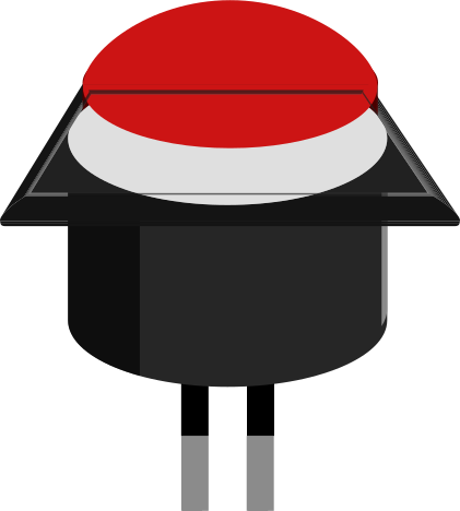
- The Push Button Round is a simple, momentary switch that allows users to make or break an electrical circuit by pressing it. When pressed, the button completes the circuit, and when released, the circuit is broken.
- Commonly used in electronic devices for user input, such as power buttons, reset switches, or control interfaces. It is also widely used in DIY electronics projects, prototyping, and embedded systems.
Explore Projects Built with Push Button Round
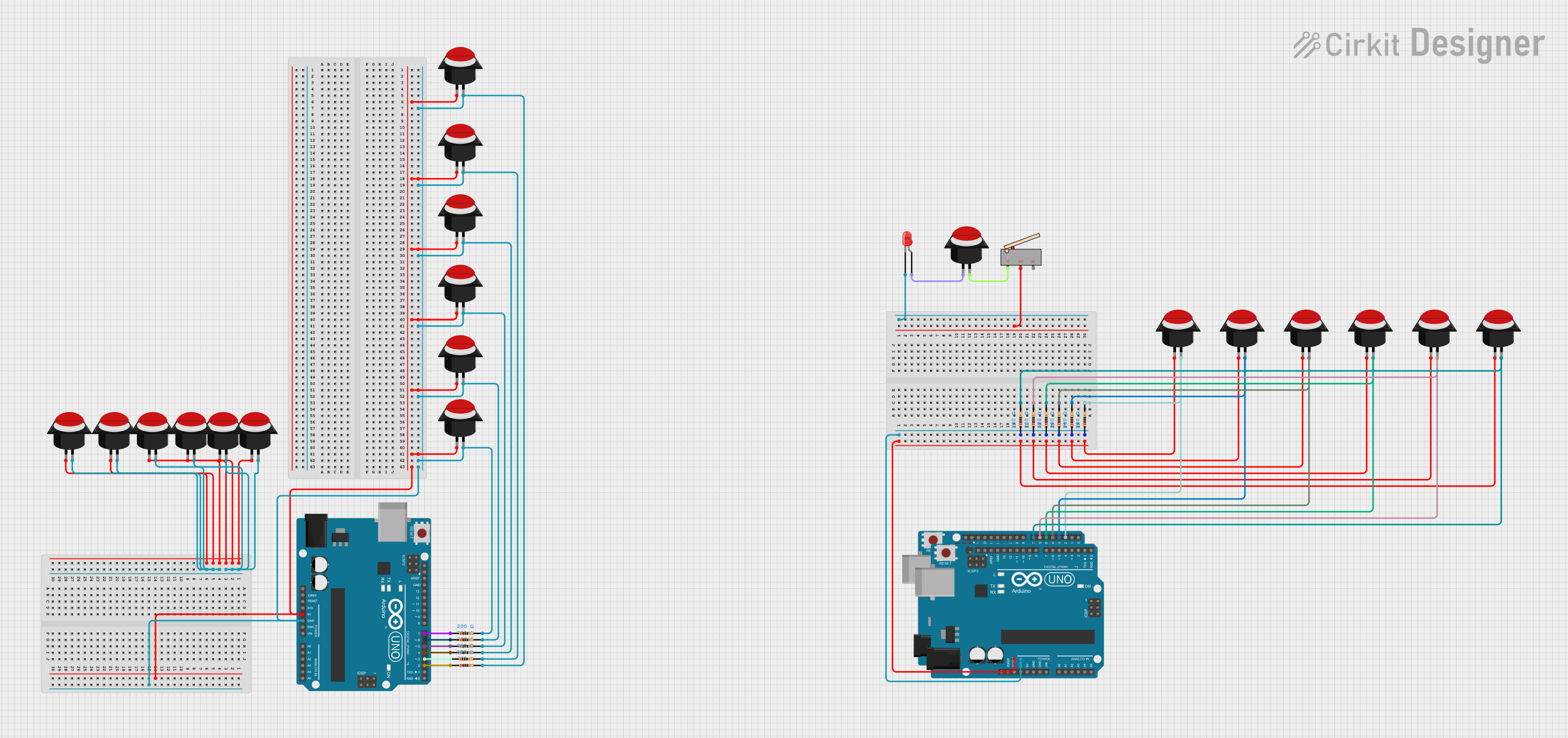

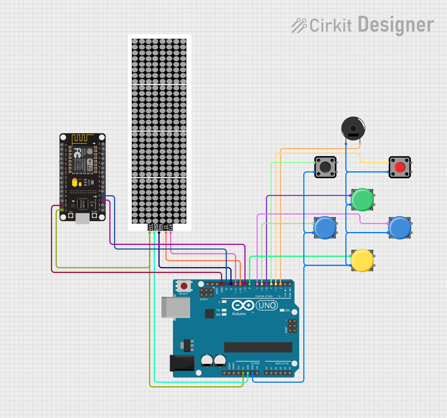

Explore Projects Built with Push Button Round
Technical Specifications
- Type: Momentary push button (normally open)
- Shape: Round
- Material: Plastic or metal housing with conductive contacts
- Voltage Rating: Typically 3V to 24V (check specific model for exact rating)
- Current Rating: Typically 50mA to 500mA
- Contact Resistance: ≤ 50mΩ
- Insulation Resistance: ≥ 100MΩ
- Operating Temperature: -20°C to +70°C
- Mounting Style: Panel mount or PCB mount
- Actuation Force: Typically 150g to 300g
Pin Configuration and Descriptions
The Push Button Round typically has two or four pins, depending on the model. Below is a description of the pin configuration:
For a 2-Pin Push Button:
| Pin Number | Description |
|---|---|
| 1 | Terminal 1 (connect to circuit) |
| 2 | Terminal 2 (connect to circuit) |
For a 4-Pin Push Button:
| Pin Number | Description |
|---|---|
| 1 | Terminal 1 (connect to circuit) |
| 2 | Terminal 2 (connect to circuit) |
| 3 | Terminal 3 (internally connected to Terminal 1) |
| 4 | Terminal 4 (internally connected to Terminal 2) |
Note: For 4-pin push buttons, terminals 1 and 3 are internally connected, as are terminals 2 and 4. This ensures flexibility in PCB design.
Usage Instructions
Connecting the Push Button:
- Identify the terminals of the push button. For a 2-pin button, connect one terminal to the power source and the other to the input of the circuit.
- For a 4-pin button, use any pair of internally connected terminals (e.g., 1 and 3, or 2 and 4).
- A pull-down resistor (typically 10kΩ) is recommended to prevent floating input signals when the button is not pressed.
Using with an Arduino UNO:
- Connect one terminal of the push button to a digital input pin on the Arduino (e.g., pin 2).
- Connect the other terminal to the ground (GND).
- Use a pull-up resistor (internal or external) to ensure a stable HIGH signal when the button is not pressed.
Sample Arduino Code:
// Push Button Example with Arduino UNO
// This code reads the state of a push button and turns on an LED when pressed.

const int buttonPin = 2;  // Pin connected to the push button
const int ledPin = 13;    // Pin connected to the onboard LED

void setup() {
  pinMode(buttonPin, INPUT_PULLUP); // Set button pin as input with internal pull-up
  pinMode(ledPin, OUTPUT);          // Set LED pin as output
}

void loop() {
  int buttonState = digitalRead(buttonPin); // Read the button state

  if (buttonState == LOW) { // Button pressed (LOW due to pull-up resistor)
    digitalWrite(ledPin, HIGH); // Turn on the LED
  } else {
    digitalWrite(ledPin, LOW);  // Turn off the LED
  }
}
- Important Considerations:
- Ensure the voltage and current ratings of the push button match your circuit requirements.
- Avoid excessive force when pressing the button to prevent damage.
- Use debounce techniques (hardware or software) to avoid false triggering due to mechanical bouncing.
Troubleshooting and FAQs
Common Issues
Button Not Responding:
- Cause: Loose or incorrect wiring.
- Solution: Double-check the connections and ensure the button terminals are properly connected.
Button Stuck in Pressed State:
- Cause: Mechanical wear or debris inside the button.
- Solution: Clean the button or replace it if damaged.
Unstable or Flickering Output:
- Cause: Mechanical bouncing of the button contacts.
- Solution: Implement a debounce circuit or software debounce in your code.
Button Works Intermittently:
- Cause: Poor contact or insufficient pull-up/pull-down resistance.
- Solution: Use a proper pull-up or pull-down resistor (e.g., 10kΩ).
FAQs
Can I use the push button with higher voltages?
- Only if the voltage is within the rated range of the button. Exceeding the rating can damage the button or cause unsafe operation.
What is the difference between a momentary and a latching push button?
- A momentary push button only stays in its active state while pressed. A latching push button stays in its active state until pressed again.
Do I need an external pull-up resistor if using an Arduino?
- No, you can use the Arduino's internal pull-up resistor by configuring the pin as
INPUT_PULLUP.
- No, you can use the Arduino's internal pull-up resistor by configuring the pin as
Can I use the push button for AC circuits?
- Only if the button is rated for AC operation. Most push buttons are designed for low-voltage DC circuits.
By following this documentation, you can effectively integrate the Push Button Round into your electronic projects!